spiral gear

Spiral bevel gears are typically made from hardened steel. The teeth of these gears are often ground for a more precise finish allowing for little sound at high speeds. You can specify left hand or right hand depending on the direction you have to run the gears

If you have a higher speed application that requires a lot of torque then spiral bevel gears are a great option. The gears operate at 90° to each other and have “spiral” shaped tooth which provides maximum tooth surface contact while rotating. With contact spread over the whole tooth the spiral bevel gear can be run much quicker than the straight tooth bevel equipment and handle harder begins and stops.

We make spiral bevel gears limited to industrial applications.

Worm gears are used in large gear reductions. Gear ratio ranges of 5:1 to 300:1 are common. The setup is designed so that the worm can change the gear, but the equipment cannot switch the worm. The angle of the worm is shallow and consequently the gear is held in place due to the friction between your two. The gear is found in applications such as for example conveyor systems in which the locking feature can become a brake or a crisis stop.

The model cross-section shows a typical placement and utilization of a worm gear. Worm gears have an inherent safety mechanism built-in to its spiral gear china design given that they cannot function in the reverse direction.

multi start worm gear

Worm Drive
Worm drives (or worm equipment sets) are right angled drives and are used in screw jacks where the input shaft reaches right angles to the lifting screw. Other kinds of right position drives are bevel gears, and hypoid gears. Worm drives satisfy the requirements of many systems and offer a compact means of decreasing velocity whilst raising torque and so are therefore ideal for use in systems utilising e.g. lifting equipment where a high gear ratio implies it could be driven by a small motor.
A worm drive contain a worm wheel and worm gear also called worm screw or just worm. The worm wheel is similar in appearance to a spur gear the worm equipment is in the type of a screw generally with a flank angle of 20°. The worm gear screw can be solitary start or possess multiple starts based on the reduction ratio of the apparatus set. The worm has a relatively few threads on a small diameter and the worm wheel a sizable number of tooth on a large diameter. This combination offers a wide range of equipment ratios typically from 4:1 to 300:1.
The low efficiency of a worm drive lends itself to applications that require intermittent instead of continuous use. The worm drive inefficiency originates from the sliding get in touch with between the teeth. Appropriate and sufficient lubrication must be put on multi start worm gear china dissipate the heat produced and decrease the wear rate. For long life the worm gear it made from a case hardened steel with a ground finish and the worm steering wheel is often created from bronze or cast iron. Other materials combinations are utilized where appropriate and in light duty applications modern non-metallic materials are deployed.
Worm Gear Assembly
Multi-Start Threads and Self-Locking
Ordinarily a screw system (such as for example that within a screw jack) is necessary never to ‘back-drive’ when the holding force is eliminated and an axial load is applied. An individual start thread is commonly used in these situations as the shallower helix position causes higher friction between threads and is usually sufficient to avoid slippage. Such a system is said to be self-locking. This assumes a statically loaded program with little or no vibration as this might cause the friction angle to be conquer and the mixture to untighten. In systems that are subject to vibration a fasten or brake is preferred to prevent back-drive.
If self-locking isn’t a requirement of something but a greater velocity of translation is a multi start thread may be used. Therefore that multiple thread forms are created on the screw shaft.
Single Start Thread: An individual helical thread shaped around a screw body. For each 360° revolution of the screw, the proper execution has advanced axially by the pitch of 1 thread. It has the same value as the pitch. In the case of an individual start thread, lead and pitch are equal.
Double Start Thread: Two thread forms. During 360° revolution the forms advance axially by the mixed pitch of two threads. Lead is normally 2x the pitch.
Triple Start Thread: 3 thread forms. During 360° revolution the forms progress axially by the combined pitch of three threads. Lead can be 3x the pitch.
Single Begin Thread, Double Begin Thread, Triple Start Thread
A multi start thread has a steeper helix angle which outcomes in less friction between your threads and for that reason such something is less likely to be self-locking. It comes after that a steeper helix permits faster translation along the threads i.e. an item utilising a multi begin thread could be tightened in fewer rotations than one using a single start thread.
Worms will be the driving equipment in a worm and worm gear set. EFFICIENCY of worm equipment drives depends to a large degree on the helix position of the worm. Multiple thread worms and gears with higher helix angle prove 25% to 50% more efficient than solitary thread worms. The mesh or engagement of worms with worm gears produces a sliding action causing considerable friction and better loss of efficiency beyond other styles of gearing. The use of hardened and surface worm swith bronze worm gears increases performance, but we’ll make them out of virtually any material you specify. The number of threads on a worm and the number of teeth on a worm gear will determine the ratio of your arranged. Ratios are dependant on dividing the number of teeth in the gear by the number of threads. Typically the quantity of threads on a worm are 1,2, and 4, but 3, 5, and 6 are out there aswell. To regulate how many threads are on your worm just look at it from the top where the threads start and count the amount of starts.
Incorporating various multi begin threaded worm shafts directly into Ever-Power screw jacks increases the linear output speed range we can offer.

miter gear

Miter gears are 1 kind of bevel gears where the two rotational axes intersect. When speaking of narrow description of bevel gears with ability to increase or decrease speed, miter gears do not have that ability because of the pair’s same quantity of teeth. Their purpose is limited to the modification in transmission direction. Because they are a kind of bevel gears, the basic characteristic of bevel gears can be found such as for example presence of gear kinds of straight cut, spiral cut and types.

Also, because the shafts could be set to any angle, right now there are miter gears with non-90 degree (non-perpendicular) angle called angular miter gears. Ever-power can be capable of creating angular miter gears with shaft angles in the number of 45 to 120 degrees.

Because a couple of straight tooth miter gears gets the same number of teeth, with the exception of minor differences such as collection screw holes and key methods, the same two gears can mate with each other. However, in the case of spiral miter gears, even when the amount of teeth will be the same, the twisting directions are different. Therefore, the same gear cannot be meshed together, and it is required to pair the proper and remaining handed pairs.

Bevel gears are classified in miter gear china different types according to geometry:

Right bevel gears have conical pitch surface area and teeth are direct and tapering towards apex.

Internal Gears

Internal gear is certainly a gear using its teeth cut 
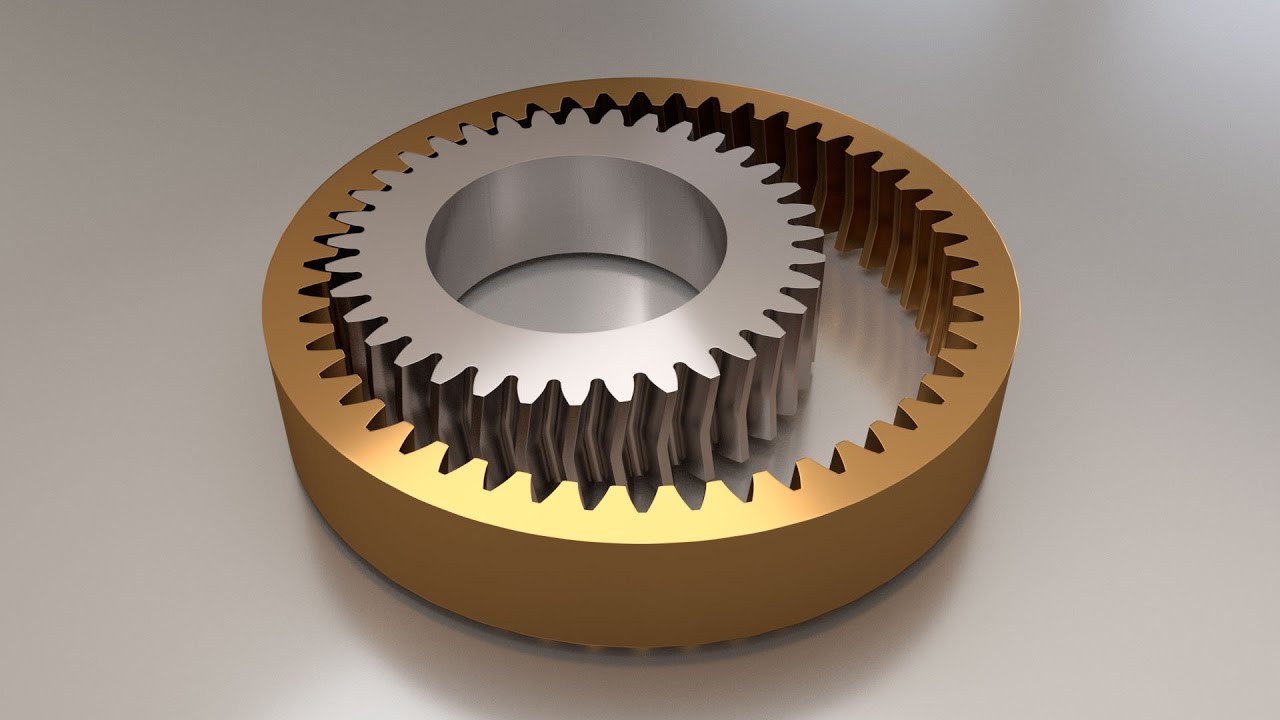
in the internal surface of a cylinder and meshes with spur gears.

In its manufacturing, because of its shape, the most common hobbing machine used in spur gear production can’t be used. Generally it is made out of gear shaper (or gear shaping machine) built with a pinion cutter. More recently, the efficiency of inner gear cutting provides been improved by a different procedure called skiving.

Because of the thinness of the band, it is sometimes difficult to produce high precision. On the other hand, gear grinding to boost precision grade is bound by the amount of manufacturers and their available grinding facilities resulting in very high cost.

Also, although it is normally too expensive to create helical teeth internal gears, Ever-Power has made it possible to produce them by adopting equipment that may cut them simply by making pinion cutters rather than needing helical guides.

Normally, internal gears can be used with the same module spur gears, based on the number of teeth combinations, but it is necessary to note the possibilities to getting involute, trochoid or trimming interferences. For using Ever-Power standard share gears, please seek advice from the PDF formatted “Specialized Information of Internal Gears” section for usable quantity of teeth combinations.

Internal gears tend to be used in applications involving planetary gear drives and gear couplings. There are three main types of planetary equipment mechanisms: planetary, solar and star types. Depending on the type and the design of which shafts become input and result, many variations of rate transmitting ratios and rotational directions are produced.

metric worm gears

Contact HZPT for metric gears and your metric component requirements. We manufacture a multitude of gears and components to metric or inch specifications. Gear types include worms, helical, spur, or bevel equipment tooth to AGMA and equivalent quality levels. We make metric gears for the next industries: aviation, defense and metric worm gears china aerospace instrumentation, commercial, energy, general market and equipment, healthcare, leisure, musical instrument, saw, scientific research and transportation.
HZPT manufactures metric gears using modern machining methods to customer specifications.
We strive to develop and keep maintaining supportive relationships with this customers. To comprehend your product requirements is important at HZPT. Allow our 50 plus years of manufacturing experience to supply you with reliable quality workmanship – metric gears of the highest quality.
This product category includes the next types of metric gears: Flat gears, ring gears, sector gears, rack and pinion gears, internal gears, face gears, metric worm gears, metric spur gears, planetary gears, cluster gears, complex gears, hub gears, gear segments, gear shafts, and gear assemblies with; worms; threads; helical, spur and bevel gear teeth, cross holes, lightening holes, holes with threads, slot machine games, etc. Non-gear components consist of: Knobs, and knob shafts, non-geared shafts, instrument ideas, pallets, and stops. All products are produced to custom requirements expressed in in . or metric measurements.

Differential Gear

Differential gear, in auto mechanics, gear arrangement that allows power from the engine to be transmitted to a set of traveling wheels, dividing the force equally between them but permitting them to follow paths of different lengths, as when turning a corner or traversing an uneven street. On a straight road the tires rotate at the same rate; when turning a part the outside wheel provides farther to move and can turn faster than the inner steering wheel if unrestrained.

The elements of the Ever-Power differential are shown in the Figure. The energy from the tranny is delivered to the bevel ring equipment by the drive-shaft pinion, both of which are held in bearings in the rear-axle housing. The case is an open boxlike framework that’s bolted to the ring gear possesses bearings to support a couple of pairs of diametrically reverse differential bevel pinions. Each wheel axle is attached to a differential side equipment, which meshes with the differential pinions. On a straight road the wheels and the side gears rotate at the same acceleration, there is no relative motion between your differential part gears and pinions, plus they all rotate as a device with the case and band gear. If the vehicle turns to the left, the right-hand wheel will be required to rotate faster compared to the left-hand wheel, and the Differential Gear medial side gears and the pinions will rotate relative to each other. The ring gear rotates at a acceleration that is add up to the mean speed of the left and right wheels. If the tires are jacked up with the tranny in neutral and among the tires is turned, the contrary wheel will turn in the opposite direction at the same rate.

The torque (turning second) transmitted to both wheels with the Ever-Power differential may be the same. Therefore, if one steering wheel slips, as in ice or mud, the torque to the other wheel is decreased. This disadvantage can be overcome somewhat by the use of a limited-slide differential. In one version a clutch connects among the axles and the band gear. When one wheel encounters low traction, its tendency to spin is certainly resisted by the clutch, hence providing higher torque for the additional wheel.
OPEN DIFFERENTIAL:
A differential in its most basic form comprises two halves of an axle with a gear on each end, linked together by a third gear making up three sides of a sq .. This is normally supplemented by a fourth gear for added power, completing the square.

Differential Gear

Every system provides it owns benefits and drawbacks, and although the more difficult systems are generally superior they have an attached cost that far exceeds the simpler systems.

The downside to the machine is it is very complicated and very expensive, and typically only used for racing/track applications coupling China because of its high speed cornering potential.

Torque Vectoring Differential 940x310The yellow-colored arrow highlights the torque transfer occuring through the part, generated by the artifical level of resistance becoming exerted by the TVD externally wheel. This enables for greater acceleration out from the corner as the car’s turning abilitty is definitely increased.

A Torque Vectoring Differential is with the capacity of channelling 100% of the available torque through a single wheel when needed in the the majority of extreme of circumstances.

With the TVD exerting more resistance onto the outside wheels clutch, it tricks the machine into diverting more torque through it – increasing the amount power that can be applied and reducing the understeer skilled under acceleration out of a corner.

By continuing to apply this resistance through the part, as the vehicle passes the apex and starts to accelerate out it will continue to override a standard multiway-LSD – which would again interpret the quicker moving outside wheel as slipping and divert torque during acceleration to the within wheel, which it perceives as having more hold.

However, instead of releasing the resistance upon both wheels a TVD continues to activate the clutch on the outside wheel only – increasing the resistance experienced by that wheel and making the machine channel more torque through it. This imbalance of capacity to the outside encourages the vehicle to turn into the part sharper and reducing understeer.

Gear Coupling

Though one may not think of gears to be versatile, gear couplings are extremely much regarded as a flexible coupling. A equipment coupling is usually a mechanical device made to transmit torque between two shafts that are not collinear. The coupling typically contains two versatile joints, one fixed to each shaft. These joints are often connected by a third shaft known as the spindle.
Each joint generally contains a 1:1 equipment ratio internal/external equipment set. The tooth flanks and outer diameter of the external gear are crowned to allow for angular displacement between your two gears. Mechanically, the gears are equivalent to rotating splines with altered profiles. They are known as gears due to the relatively huge size of the teeth. Gear couplings are usually limited to angular misalignments of 4 to 5°.
Gear couplings ordinarily can be found in two variations, flanged sleeve and continuous sleeve. Flanged equipment couplings consist of brief sleeves encircled by a perpendicular flange. One sleeve is positioned on each shaft therefore the two flanges fall into line face to face. A number of screws or bolts in the flanges keep them collectively. Continuous sleeve gear couplings feature shaft ends coupled jointly and abutted against each other, which are then enveloped by a sleeve. Generally, these sleeves are constructed with metal, but they can also be made of Nylon.
Single joint equipment couplings are used to connect two nominally coaxial shafts. In this software the device is called a gear-type versatile, or versatile coupling. The solitary joint allows for minimal misalignments such as for example installation errors and changes in shaft alignment because of operating conditions. These types of gear couplings are generally limited to angular misalignments of 1/4 to 1/2°.

Gear couplings are torsionally rigid and so are supplied to two designs – completely flexible and flexible/rigid. A totally versatile coupling comprises two hubs with an external gear and two outer sleeves with an interior gear. It’s a universal coupling for a variety of applications and accommodates all feasible misalignments (angular, offset and combined) along with large axial moments. Machines, bearings, seals, and shafts are therefore not subjected to the excess forces, sometimes of considerable magnitude, which occur from unavoidable misalignment usually connected with rigid shaft couplings.
A flexible/rigid coupling comprises one flexible geared half and one rigid fifty percent. It does not accommodate parallel displacement of shafts but will accommodate angular misalignment. This type of couplings are primarily utilized for “floating shaft” applications.
Sizes 010 – 070 all have crowned teeth with a 20° pressure contact. This allows to accommodate up to 1 1,5° static angular misalignment per gear mesh. However, reducing the operational misalignment will increase the life of the coupling along with the life of additional machinery components such as for example bearings etc.

SERIES H Features & Benefits

Higher Misalignment Capability
Sizes 1-7 compensate for up to ±1 1/2° static angular misalignment per gear mesh.
Minimizing working misalignment will increase the life of the coupling. Make reference to the Set up and Alignment Instructions for alignment recommendations.
Larger Bore Capabilities permit the most economical size selection for shafts up to 10 5/8″.
Higher Torque Ratings due to bigger tooth pitch diameters than other couplings.
Versatility for the reason that Series H’s are interchangeable by half coupling with competitive coupling designs.
1 1/2° Curved-Face Teeth are a primary feature of the Series H coupling, sizes 1-7. The crowned hub teeth are a 20° full-depth involute tooth type with flank, tip, and root curvature. When
used in combination with the straight confronted sleeve teeth, these 1 1/2° curved encounter hubs offer elevated shaft misalignment capability
CENTER FLANGE BOLTING
All couplings feature precision-drilled flange bolt holes, and tight tolerance Grade 5 flange bolts to assure a long-enduring flange to flange and fastener fit. Exposed bolt flanges are
regular. Shrouded bolt flanges could be supplied through size 5. Size #5 1/2 and larger couplings are only obtainable with uncovered bolt flanges.

LUBRICATION
Each sleeve flange is supplied with two pipe plugs 180° aside. This permits assembly of a complete flex coupling with four lube plugs positioned every 90°, facilitating lubrication. The lube seal is a Buna-N O-ring to greatly help retain grease and exclude contaminants. KHP or KSG coupling greases are recommended in order to obtain maximum operating life.

Ever-power COUPLING Features & Benefits

The Ever-power gear coupling is available in two basic product lines:

Ever-powercoupling for medium to heavy-duty applications
Sizes 1 1/2 through 7 with integral end ring.
Sizes 8 through 30 with bolt-on end band.

stainless collar

We are involved in offering a remarkable selection of stainless steel collar317 to our valuable clients. They are available in various size according to customer demand. STAINLESS 317 Collar Buttweld Fittings, STAINLESS 317Collar Buttweld Fittings Pipe Fittings, STAINLESS Stainless Steel 317 Collar Buttweld Fittings, Steel Stainless Steel 317 Collar Buttweld Fittings Pipe Fittings, etc in different estimations to meet up the shifting necessities of grouped endeavors. Exceptional emphasis can be laid on the thought of these Stainless Steel 317 Collar Buttweld Fittings and along these lines, we execute stringent quality control philosophy that conforms to Worldwide Standards. These Stainless Steel 317 Collar Buttweld Fittings are made using ensured metal acquired from solid suppliers. STAINLESS 317 Collar Buttweld Fittings that are offered in different conclusions. The number we offer consolidates STAINLESS Stainless Steel 317 Collar Buttweld Fittings, Carbon Steel Socketweld Fittings, and Alloy Steel Socketweld Fittings. These are delivered making use of assessed materials to meet up the customer”s wants and requirements. Our things are notable for their high flexibility, bother free make use of and strength.
· Setscrew shaft collar for applications assisting low axial loads and basic positioning
· Effective on shafts made of softer material than the setscrew material
· Stainless metal 303 for greater corrosion resistance than steel or aluminum
· Includes a forged setscrew for securing the collar onto the shaft
· Operating temperatures range between -40 to 176 degrees C (-40 to 350 degrees F)
· This Ruland setscrew shaft collar is made of stainless steel 303. It really is a setscrew-type shaft collar for applications supporting low axial loads and basic positioning. Setscrew collars have improved keeping power when the shaft materials is softer compared to the setscrew material. It is made of stainless 303 for greater resistance to corrosion than metal or aluminum. This collar comes with a forged setscrew for securing the collar onto the shaft. The operating temperatures for this collar range from -40 to 176 degrees C (-40 to 350 degrees F). This shaft collar is ideal for use in a variety of applications, including in the automotive industry to situate components in vehicle power steering assemblies, the production industry to locate components on a conveyor belt system, and the hobby craft Stainless Collar sector to hold wheels on axles in remote control vehicles, among others.
·
· Shaft collars are ring-shaped devices mainly used to secure parts onto shafts. In addition they provide as locators, mechanical stops, and spacers between various other components. The two simple types of shaft collars are clamping (or split) collars, that can come in one- or two-piece styles, and setscrew collars. In both types, a number of screws contain the collars in place on the shaft. In setscrew collars, screws are tightened through the collar until they press straight against the shaft, and in clamping collars, screws are tightened to uniformly compress the collar around the shaft without impinging or marring it. Setscrew collars and one-piece clamping collars should be installed by sliding the collar over the finish of the shaft, while two-piece clamping collars individual into two halves and will be installed between components on the shaft. Shaft collars are produced from an array of materials including zinc-plated steel, light weight aluminum, nylon, and neoprene. Within nearly every type of machinery and sector, shaft collars are found in applications including gearbox assemblies, motor bases, machine tools, drive shafts, agricultural implements, medical apparatus, and paper and metal mill equipment, amongst others.
·
· Ruland manufactures shaft collars, rigid couplings, and zero-backlash movement control couplings including beam couplings, bellows couplings, Oldham couplings, curved jaw couplings, and miniature disc couplings. The company, founded in 1937, and headquartered in Marlborough, MA, complies with Restriction of Hazardous Substances (RoHS) and Registration, Evaluation, Authorization, and Restriction of Chemical substances (REACH) standards.
· LCM-8-SS Stainless Steel Double Split Shaft Collar 8mm (8x18x9)
·
· Stainless Metal for corrosion resistance complete with stainless steel screws.
·
· Our selection of shaft collars certainly are a cost effective solution to positioning parts or offering a stop placement on a shaft.
·
· Dual split (2 piece) collars are suited to applications where you are struggling to slide the collar on from the end of the shaft. They could be situated in between existing items saving enough time of dismantling the complete shaft.
Split Clamping Collars Stainless Steel, or Stainless Steel Split Arranged Collars, can be utilized as end stops, for fixing elements or clamping. These Stainless Clamping Collars are 303 stainless steel with stainless grub screws. Precision clamping collars eliminate risk of damage to the shaft surface, also during high clamping forces.
Simple set up and adjustment
Clamp grips shaft without departing score marks
Stainless steel for extra corrosion resistance
Hugs the shaft with all round grip
Effective on hardened or plain shafts
Clamp-style and set screw shaft collars from Grainger can be indispensable to power transmission. They are able to keep bearings and sprockets on shafts, situate elements in engine and gearbox assemblies and serve as mechanical stops. A two-piece clamping shaft collar can certainly wrap around a hard or soft shaft without marring. Set screw collars use a cup stage socket set screw to lock onto a gentle or predrilled shaft.
Allows assembly / disassembly on and off the shaft without the need to remove other ancillary parts. Clamps firmly in place once tightened to the shaft. Ideal for positioning parts such as for example bearings or sprockets onto shafts.
§ Manufactured with plain finish maintaining bore size: 7/16″, outside diameter: 15/16″ and width: 3/8″.
§ Best suited for shafting applications that require greater axial load capability.
§ Stainless steel construction helps it endure cleaning with detergents and large wash-downs using industrial cleaning solutions.
§ Perfect for make use of in food processing, medical, and pharmaceutical industries.
§ Fabricated with a shiny polished complete for added safety when used in the toughest environmental conditions.
§ Designed to wrap around the shaft for even distribution of clamping forces.
§ It is definitely stamped with bore size, which helps in easy identification during maintenance and substitute.
§ Precision engineered to ensure a tight fit
§ Superior fit, complete, and remarkable holding power.
§ Safely secure elements onto a shaft.
§ Produced with collar width: 5/16″, bore diameter: 5/16″ and outside diameter: 11/16″.
§ Ideal for use in rugged conditions of construction, refinery, production, and automotive industries.
§ Possesses exceptional holding power, making it ideal for use with hard and soft shafts.
§ Easy to put together and disassemble.
§ Recognized in the worldwide market due to its ability to distribute power uniformly and consistently around the circumference of the shaft.
§ Performance is certainly unaffected when in touch with hydrocarbon solutions.
Climax Part C-150-S Set Screw Collar is manufactured with T303 STAINLESS, which is effective in corrosive environments. Sizes are 1-1/2 ID, 2-1/4 in. OD, 3/4 in. Width. It is effective on hard and soft shafts. It is a Cost effective collar design and quickly installed where major disassembly would otherwise be required.
· Effective on hard and soft shafts
· Cost effective collar design
· Easily installed where major disassembly would otherwise be required
· T316 stainless is highly effective in corrosive environments

Flexible coupling

Ever-power Helical Couplings, or beam couplings, are another type of flexible coupling allowing for axial motion, angular misalignment and parallel offset. This coupling design features one-piece construction leading to zero backlash. The coupling is manufactured flexible by removing material from the piece in a spiral pattern. Ever-power Helical Couplings can be found in aluminum and stainless steel.

For position precision and vibration reduction in a servo system, these couplings solve misalignment problems in response-mandatory servo systems designed for the
semiconductor manufacturing equipment market, scanning equipment and several automation applications. Standard sizes available in bores 3 mm thru 16 mm
Commercial and Accuracy Helical Couplings

Flexible Couplings be capable of compensate for shaft misalignment and so are designed to accommodate various types of load conditions. Nobody type of coupling can provide the universal solution to all or any coupling problems; therefore many designs are available, each possessing structure features to accommodate a number of types of application requirements. Ever-power offers many styles of versatile couplings, such as bellows couplings, helical couplings, Oldham couplings, common joints, and flexible shafts
Precision Flexible Antivibration Couplings

Commercial & Precision Flexible Couplings

Ever-power Bellows Couplings are flexible couplings designed to accommodate numerous kinds of load conditions. Ever-power Hi-Flex Bellows Couplings are utilized for applications which need large amounts of shaft misalignment coupled with low resultant radial loads on the bearings. Ever-power Modular Bellows Couplings are configurable and offer high torsional rigidity for high speed torque transmission. A wide variety of bore sizes and combinations can be found to accommodate specific needs.