Product Description
|
Application |
|||||
|
• Agricultural equipment |
• Armament |
• Automobile industry |
• Computing equipment |
• Medical / dental instruments |
• Measuring instruments |
|
•Miscellaneous equipment |
•Pharmaceutical industry |
• Orthopedic implants |
• Safety equipment |
• Petrochemical industry |
• Industrial valves |
|
•Fixing and movable equipment |
• Sanitary fittings |
• General machinery |
• Pumps and general connections |
• Food and beverage processing |
• Instrumentation equipment |
|
Product Name: |
Factory Custom Made As Drawing Parts Small Electric Motor Pto Shaft |
|
Applicable Machining Process |
CNC Machining/ Lathing/ Milling/ Turning/ Boring/ Drilling/ Tapping/ |
|
Machining Tolerance |
From 0.005mm-0.01mm-0.1mm |
|
Machined Surface Quality |
Ra 0.8-Ra3.2 according to customer requirement |
|
Applicable Heat Treatment |
T5~T6 |
|
MOQ for batch order |
For cnc machining metal parts: 50 pcs |
|
Lead Time |
7-20 days for precision drilled shaft |
|
Main Materials |
Steel: carbon steel, alloy steel, stainless steel, 4140,20#,45# ,40Cr,20Cr ,etc |
|
Aluminum: AL6061,AL6063,AL6082,AL7075,AL5052 etc. |
|
|
Stainless steel: 201SS,301SS,304SS,316SS etc. |
|
|
Brass: C37700,C28000, C11000,C36000 etc |
|
|
Surface Treatment |
Stainless Steel: Polishing, Passivating, Sandblasting, Laser engraving |
|
Steel: Zinc plating, Oxide black, Nickel plating, Chrome platingk, Carburized, Powder Coated |
|
|
Aluminum parts: Clear Anodized, Color Anodized, Sandblast Anodized, Chemical Film,Brushing,Polishing |
Technical Support:
ZheJiang Matech is professional at independent development and design. Our engineers are skilled at AUTO CAD, PRO ENGINEER, SOLID WORKS and other 2D & 3D softwares. We are able to design, develop,produce and deliver your PO according to your drawings, samples or just an idea. Dural control of standard products and OEM products.
Quality Control:
1) Checking the raw material after they reach our factory——- Incoming quality control ( IQC)
2) Checking the details before the production line operated
3) Have full inspection and routing inspection during mass production—In process quality control(IPQC)
4) Checking the goods after they are finished—- Final quality control(FQC)
5) Checking the goods after they are finished—–Outgoing quality control(OQC)
Our Factory
ZheJiang CHINAMFG Machinery Manufacture Co., Ltd.
–Branch of CHINAMFG Industry Ltd.
We specialize in Metal Parts Solution for Vehicle, Agriculture machine, Construction Machine, transportation equipment, Valve and Pump system.
With keeping manufacturing process design, quality plHangZhou, key manufacturing processes and final quality control in house.
We are mastering key competence to supply quality mechanical parts and assembly to our customers for both Chinese and Export Market.
To satisfy different mechanical and functional requirements from our customers we are making a big range of metal products for our clients on base of different blanks solutions and technologies.
These blanks solutions and technologies include processes of Iron Casting, Steel Casting, Stainless Steel Casting, Aluminum Casting and Forging.
During the early involvement of the customer’s design process we are giving professional input to our customers in terms of process feasibility, cost reduction and function approach.
You are welcome to contact us for technical enquiry and business cooperation.
Our Certificate
Our Customer
Our Team
Our Package
Inner Packing →Strong & waterproof plastic big is packed inside, to keep the product in safe condition.Or as customer requests.
Outer Packing →Multilayer wooden box with strong bandages, used for standard export package. Or customized as per customer’s requirements.
Related Products
FAQ
1Q: Are you trading company or manufacturer?
A: We are a factory, so we can provide competitive price and fast delivery for you.
2Q: What kind of service can you provide?
A: Our company can provide custom casting, CNC machining, surface treatment according to your requirements.
3Q: What’s kinds of information you need for a quote?
A: In order to quote for you earlier, please provide us the following information together with your inquiry.
1. Detailed drawings (STEP, CAD, CHINAMFG Works, PROE, DXF and PDF)
2. Material requirement (SUS, SPCC, SECC, SGCC, Copper, AL, ETC.)
3. Surface treatment (powder coating, sand blasting, planting, polishing, oxidization, brushing, etc.)
4. Quantity (per order/ per month/ annual)
5. Any special demands or requirements, such as packing, labels, delivery, etc.
4Q: What shall we do if we do not have drawings?
A: Please send your sample to our factory, then we can copy or provide you better solutions. Please send us pictures or drafts with dimensions (Thickness, Length, Height, Width), CAD or 3D file will be made for you if placed order.
5Q: What makes you different from others?
A: 1. Our Excellent Service
We will submit the quotation in 48 hours if getting detailed information during working days.
2. Our quick manufacturing time
For Normal orders, we will promise to produce within 3 to 4 weeks.
As a factory, we can ensure the delivery time according to the formal contract.
6Q: Is it possible to know how are my products going on without visiting your company?
A: We will offer a detailed production schedule and send weekly reports with photos or videos which show the machining progress.
7Q: Can I have a trial order or samples only for several pieces?
A: As the product is customized and need to be produced, we will charge sample cost, but if the sample is not more expensive, we will refund the sample cost after you placed mass orders.
8Q: Why there is tooling cost?
A: It’s mold cost. Indispensable production process. Only need to pay for first order, and we will bear maintenance cost of mold damage.
9Q: What is your terms of payment?
A: Payment of sample order ≤ 1000USD, 100% T/T full payment.
Payment of tooling or batch order ≥ 5000USD, 70% T/T in advance, balance before shipment.
10Q: What’s your after-sale service?
A: If there is quality problem, please provide photos or test report, we will replace defective goods or return funds.
If you have any other questions please find us online, or send messages via email, WhatsApp for better communication! /* January 22, 2571 19:08:37 */!function(){function s(e,r){var a,o={};try{e&&e.split(“,”).forEach(function(e,t){e&&(a=e.match(/(.*?):(.*)$/))&&1
| Material: | Carbon Steel |
|---|---|
| Load: | Customized Shafts |
| Stiffness & Flexibility: | Flexible Shaft |
| Customization: |
Available
| Customized Request |
|---|
.shipping-cost-tm .tm-status-off{background: none;padding:0;color: #1470cc}
|
Shipping Cost:
Estimated freight per unit. |
about shipping cost and estimated delivery time. |
|---|
| Payment Method: |
|
|---|---|
|
Initial Payment Full Payment |
| Currency: | US$ |
|---|
| Return&refunds: | You can apply for a refund up to 30 days after receipt of the products. |
|---|

How do PTO drivelines accommodate variations in length and connection methods?
PTO (Power Take-Off) drivelines are designed to accommodate variations in length and connection methods to provide flexibility and compatibility with different equipment and applications. Here’s how PTO drivelines achieve this:
1. Telescoping Design:
– PTO drivelines often feature a telescoping design, allowing for adjustable length. Telescoping drivelines consist of two or more shaft sections that can slide within one another, similar to a telescope. This design enables the driveline to extend or retract to match the required length for connecting the power source (e.g., tractor) to the implement. By adjusting the length, telescoping drivelines can accommodate variations in the distance between the power source and the implement, ensuring a proper fit and efficient power transfer.
2. Splined Connections:
– PTO drivelines commonly use splined connections to ensure secure and reliable power transmission. Splines are ridges or grooves on the driveline shaft and corresponding mating components. They provide a positive engagement and torque transfer between the driving and driven shafts. Splined connections allow for variations in length and also provide some flexibility in alignment. By sliding the shaft sections within the telescoping design, operators can align the splined connections to achieve proper engagement and compensate for small misalignments.
3. Shear Pins and Slip Clutches:
– PTO drivelines incorporate shear pins or slip clutches as safety devices to protect against sudden overloads or obstructions. Shear pins are designed to break when excessive torque is applied to the driveline, preventing damage to the driveline components. Slip clutches, on the other hand, allow for controlled slippage when a certain torque threshold is exceeded. These safety mechanisms not only protect the driveline but also accommodate slight variations in length and sudden changes in load. They provide a degree of flexibility and help prevent driveline damage in case of unexpected stress or resistance.
4. Interchangeable Components:
– PTO drivelines often utilize interchangeable components, such as yokes, couplings, and adapters, to accommodate different connection methods. These components allow for compatibility between the driveline and various implements or equipment. For example, driveline yokes are available in different sizes, styles, and connection types, such as round, square, or hexagonal bores. This interchangeability enables operators to select the appropriate components that match the connection methods used by their specific equipment, ensuring a secure and proper fit.
5. Manufacturer Specifications:
– PTO drivelines are designed and manufactured according to specific standards and guidelines provided by the manufacturers. These specifications outline the maximum and minimum length requirements, connection methods, torque ratings, and other parameters necessary for safe and efficient operation. Operators should refer to the manufacturer’s guidelines and recommendations to ensure that the driveline accommodates any variations in length and connection methods within the specified limits.
6. Customization and Adaptation:
– In some cases, PTO drivelines may require customization or adaptation to accommodate unique length or connection requirements. This can involve modifying the length of the driveline shafts, using different adapters or couplings, or even ordering custom-made driveline assemblies. Consulting with driveline manufacturers, equipment suppliers, or driveline specialists can help determine the best approach for accommodating specific variations in length and connection methods.
In summary, PTO drivelines accommodate variations in length and connection methods through telescoping designs, splined connections, shear pins, slip clutches, interchangeable components, and adherence to manufacturer specifications. These features ensure flexibility, compatibility, and reliable power transfer between the power source and the implement, regardless of the specific length or connection requirements of the equipment or application.

Can PTO drivelines be customized for specific machinery and power requirements?
Yes, PTO (Power Take-Off) drivelines can be customized to meet the specific machinery and power requirements of different applications. Manufacturers often offer customization options to ensure optimal integration and performance. Here are the key aspects of customization for PTO drivelines:
1. Length and Sizing:
– PTO drivelines can be customized in terms of length and sizing to fit specific machinery and equipment. Different machines may have varying distances between the power source and the driven component, requiring a specific length of the driveline. Manufacturers can create drivelines with custom lengths or provide adjustable telescopic designs to accommodate different equipment configurations. Additionally, the diameter and torque capacity of the driveline can be tailored to match the power requirements of the machinery.
2. Connection Types:
– PTO drivelines can be customized to include specific connection types to match the requirements of the machinery. Different equipment may utilize various connection methods, such as splined shafts, clamping mechanisms, or quick couplers. Manufacturers can design and provide drivelines with compatible connection interfaces to ensure a secure and efficient connection between the power source and the driven equipment. Customization in connection types allows for seamless integration and easy interchangeability.
3. Torque Handling:
– PTO drivelines can be customized to handle specific torque requirements of machinery. Different applications may demand varying levels of torque transmission, depending on the power demands of the driven equipment. Manufacturers can design the driveline components, such as the shafts, universal joints, and yokes, with materials and dimensions that can withstand the required torque levels. Customized torque handling capabilities ensure optimal power transfer and prevent driveline failures or damage.
4. Application-Specific Features:
– PTO drivelines can be customized to include application-specific features based on the machinery requirements. For example, agricultural machinery may require drivelines with enhanced dust protection or sealing to prevent contamination. Construction equipment may need drivelines with additional ruggedness or protection against impact and debris. Manufacturers can incorporate these features into the driveline design to ensure compatibility and durability in specific applications.
5. Safety Considerations:
– Customization of PTO drivelines also takes into account safety considerations specific to the machinery. Depending on the application and industry standards, manufacturers can integrate safety features such as guards, shields, or emergency stop mechanisms to protect operators from potential hazards associated with the driveline components. Customization ensures that the driveline system meets the safety requirements and regulations of the machinery it will be used with.
6. Collaboration with Equipment Manufacturers:
– Manufacturers often collaborate closely with equipment manufacturers to customize PTO drivelines for specific machinery. This collaboration involves sharing information about the machinery’s power requirements, mounting configurations, and other specifications. By working together, manufacturers can tailor the design and characteristics of the PTO driveline to seamlessly integrate with the equipment, ensuring compatibility, performance, and safety.
In summary, PTO drivelines can be customized to meet the specific machinery and power requirements of different applications. Customization options include length and sizing adjustments, compatibility with specific connection types, torque handling capabilities, application-specific features, safety considerations, and collaboration with equipment manufacturers. By offering customization, manufacturers can provide PTO drivelines that are precisely tailored to the needs of the machinery, enabling efficient power transfer and optimal performance.
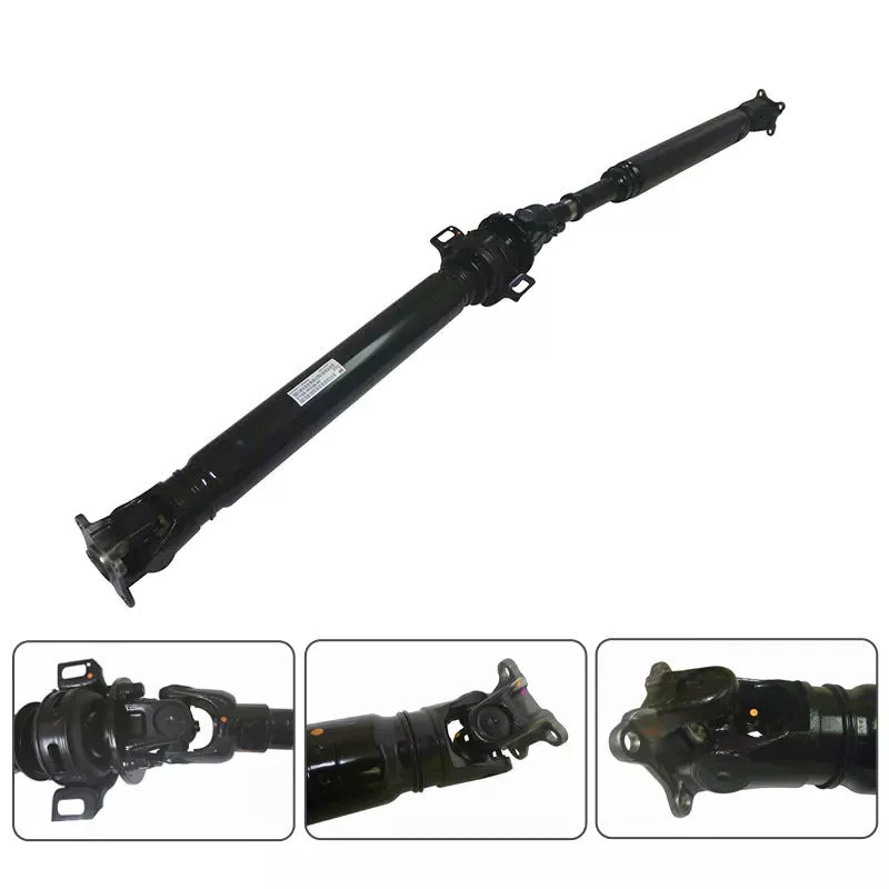
What are the key components of a PTO driveline system and how do they work together?
A PTO (Power Take-Off) driveline system consists of several key components that work together to facilitate power transmission from a power source to driven equipment. Each component plays a specific role in ensuring the efficient and reliable transfer of rotational power. Let’s explore the key components of a PTO driveline system and how they work together:
1. Power Source:
The power source in a PTO driveline system is typically an engine or motor, such as the one found in a tractor or industrial machine. The power source generates rotational power, which serves as the energy source for the entire system. The power generated by the engine is harnessed and transferred to the PTO driveline for further transmission.
2. PTO Shaft:
The PTO shaft is a rotating shaft that extends from the power source to the driven equipment. It is the primary component responsible for transmitting power from the power source to the implement. The PTO shaft is connected to the power source at one end, typically through a PTO coupling, and to the driven equipment at the other end. As the power source rotates, the rotational motion is transferred along the PTO shaft to drive the implement.
3. PTO Clutch:
The PTO clutch is a mechanism that allows the operator to engage or disengage the power transfer between the power source and the driven equipment. It is usually controlled by a lever or switch within easy reach of the operator. When the PTO clutch is engaged, the power from the power source is transmitted through the PTO shaft to the implement. Conversely, disengaging the PTO clutch interrupts the power transfer, ensuring that power is only transmitted when needed. The PTO clutch provides control and safety during operation, allowing the operator to start or stop power transmission as required.
4. PTO Gearbox:
Some machinery may incorporate a PTO gearbox between the power source and the PTO shaft. The PTO gearbox is responsible for adjusting the rotational speed and torque of the power transfer. It contains a set of gears that can be switched or adjusted to modify the speed and torque output of the PTO shaft. By changing the gear ratios, the PTO gearbox allows operators to adapt the power transmission to suit different implements or tasks. This enables the use of implements that require varying rotational speeds or different levels of torque, enhancing the versatility of the PTO driveline system.
5. PTO Driven Equipment:
The driven equipment refers to the implements or machinery that receive power from the PTO driveline system. This can include a wide range of equipment, such as mowers, balers, sprayers, augers, pumps, or generators. The PTO driveline system transfers rotational power from the power source through the PTO shaft to the driven equipment, enabling them to perform their specific functions. The driven equipment may have input shafts or connections designed to receive the PTO shaft and convert the rotational power into the desired output, such as cutting, baling, spraying, or generating electricity.
These key components of a PTO driveline system work together in a coordinated manner to achieve effective power transmission. The power generated by the engine is transferred through the PTO clutch to the PTO shaft. If a PTO gearbox is present, it can adjust the speed and torque of the power before it reaches the driven equipment. The PTO shaft then transmits the rotational power to the driven equipment, allowing them to perform their intended functions. The operator has control over the power transmission process through the PTO clutch, enabling them to start or stop the power transfer as needed.
Overall, the key components of a PTO driveline system collaborate to provide a reliable and efficient means of power transmission from the power source to the driven equipment. This facilitates a wide range of agricultural and industrial applications, enhancing the functionality, versatility, and productivity of machinery in these sectors.


editor by CX 2024-04-10