คำอธิบายผลิตภัณฑ์
CE Certificate Agricultural Machinery Potato Harvester Spare Parts Cardan Pto Drive Shaft and Farm Tractor Pto Shaft
คำอธิบายผลิตภัณฑ์
A Power Take-Off shaft (PTO shaft) is a mechanical device utilized to transmit power from a tractor or other power source to an attached implement, such as a mower, tiller, or baler. Typically situated at the rear of the tractor, the PTO shaft is driven by the tractor’s engine through the transmission.
The primary purpose of the PTO shaft is to supply a rotating power source to the implement, enabling it to carry out its intended function. To connect the implement to the PTO shaft, a universal joint is employed, allowing for movement between the tractor and the implement while maintaining a consistent power transfer.
Here is our advantages when compare to similar products from China:
1.Forged yokes make PTO shafts strong enough for usage and working;
2.Internal sizes standard to confirm installation smooth;
3.CE and ISO certificates to guarantee to quality of our goods;
4.Strong and professional package to confirm the good situation when you receive the goods.
Product Specifications
In farming, the most common way to transmit power from a tractor to an implement is by a driveline, connected to the PTO (Power Take Off) of the tractor to the IIC(Implement Input Connection). Drivelines are also commonly connected to shafts within the implement to transmit power to various mechanisms.
The following dimensions of the PTO types are available.
Type B:13/8″Z6(540 min)
Type D:13/8″Z21(1000 min)
Coupling a driveline to a PTO should be quick and simple because in normal use tractors must operate multiple implements. Consequently, yokes on the tractor-end of the driveline are fitted with a quick-disconnect system, such as push-pin or ball collar.
Specifications for a driveline, including the way it is coupled to a PTO, depend CZPT the implement.
Yokes on the llc side are rarely disconnected and may be fastened by quick-lock couplings (push-pin or ball collar).
Taper pins are the most stable connection for splined shafts and are commonly used in yokes and torque limiters. Taper pins are also often used to connect internal drive shafts on drivelines that are not frequently disconnected.
Torque limiter and clutches must always be installed on the implement side of the primary driveline.
Packaging & Shipping
Company Profile
HangZhou Hanon Technology Co.,ltd is a modern enterprise specilizing in the development,production,sales and services of Agricultural Parts like PTO shaft and Gearboxes and Hydraulic parts like Cylinder , Valve ,Gearpump and motor etc..
We adhere to the principle of ” High Quality, Customers’Satisfaction”, using advanced technology and equipments to ensure all the technical standards of transmission .We follow the principle of people first , trying our best to set up a pleasant surroundings and platform of performance for each employee. So everyone can be self-consciously active to join Hanon Machinery.
FAQ
1.WHAT’S THE PAYMENT TERM?
When we quote for you,we will confirm with you the way of transaction,FOB,CIFetc.<br> For mass production goods, you need to pay 30% deposit before producing and70% balance against copy of documents.The most common way is by T/T.
2.HOW TO DELIVER THE GOODS TO US?
Usually we will ship the goods to you by sea.
3.HOE LONG IS YOUR DELIVERY TIME AND SHIPMENT?
30-45days.
Other Products
/* March 10, 2571 17:59:20 */!function(){function s(e,r){var a,o={};try{e&&e.split(“,”).forEach(function(e,t){e&&(a=e.match(/(.*?):(.*)$/))&&1
| Type: | Pto Shaft |
|---|---|
| Usage: | Agricultural Products Processing, Farmland Infrastructure, Tillage, Harvester, Planting and Fertilization, Grain Threshing, Cleaning and Drying, Agricultural Machinery,Farm Tractor |
| Material: | 45cr Steel |
| Samples: |
US$ 20/Piece
1 Piece(Min.Order) | Order Sample |
|---|
| Customization: |
Available
| Customized Request |
|---|
.shipping-cost-tm .tm-status-off{background: none;padding:0;color: #1470cc}
|
Shipping Cost:
Estimated freight per unit. |
about shipping cost and estimated delivery time. |
|---|
| Payment Method: |
|
|---|---|
|
Initial Payment Full Payment |
| Currency: | US$ |
|---|
| Return&refunds: | You can apply for a refund up to 30 days after receipt of the products. |
|---|
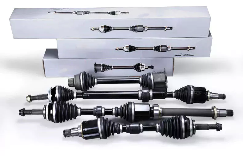
ระบบส่งกำลังช่วยให้การส่งกำลังเป็นไปอย่างเหมาะสมที่สุด ในขณะเดียวกันก็ลดการสูญเสียพลังงานให้น้อยที่สุดได้อย่างไร?
ระบบส่งกำลังมีบทบาทสำคัญในการทำให้การส่งกำลังจากเครื่องยนต์ไปยังล้อเป็นไปอย่างเหมาะสมที่สุด พร้อมทั้งลดการสูญเสียพลังงานให้น้อยที่สุด การออกแบบและส่วนประกอบของระบบส่งกำลังได้รับการออกแบบอย่างพิถีพิถันเพื่อเพิ่มประสิทธิภาพสูงสุดและลดการสูญเสียพลังงานให้น้อยที่สุด ต่อไปนี้คือปัจจัยสำคัญบางประการที่ช่วยให้การส่งกำลังเป็นไปอย่างเหมาะสมที่สุดและลดการสูญเสียพลังงานภายในระบบส่งกำลังให้น้อยที่สุด:
1. การส่งกำลังไฟฟ้าอย่างมีประสิทธิภาพ:
ระบบส่งกำลังใช้ส่วนประกอบต่างๆ เช่น เกียร์ คลัตช์ และทอร์คคอนเวอร์เตอร์ เพื่อส่งกำลังจากเครื่องยนต์ไปยังล้อ ส่วนประกอบเหล่านี้ได้รับการออกแบบมาเพื่อลดการสูญเสียพลังงานโดยการลดแรงเสียดทาน ปรับปรุงประสิทธิภาพการทำงานของเฟือง และเพิ่มประสิทธิภาพการส่งแรงบิด ตัวอย่างเช่น การใช้วัสดุที่มีแรงเสียดทานต่ำ เช่น ตลับลูกปืนแบบลูกกลิ้ง และการใช้การออกแบบเฟืองขั้นสูง เช่น เฟืองเกลียวหรือเฟืองไฮปอยด์ สามารถช่วยลดการสูญเสียพลังงานเนื่องจากแรงเสียดทานและการทำงานของเฟืองได้
2. การปรับอัตราทดเกียร์ให้เหมาะสม:
การเลือกอัตราทดเกียร์ที่เหมาะสมเป็นสิ่งสำคัญอย่างยิ่งต่อการส่งกำลังอย่างมีประสิทธิภาพสูงสุด การเลือกอัตราทดเกียร์ที่ตรงกับลักษณะกำลังของเครื่องยนต์และสภาพการขับขี่ของรถ จะช่วยให้ระบบส่งกำลังสามารถแปลงและส่งกำลังไปยังล้อได้อย่างมีประสิทธิภาพ อัตราทดเกียร์ที่เหมาะสมจะช่วยให้เครื่องยนต์ทำงานในช่วงรอบการหมุนที่เหมาะสมที่สุด ลดการสูญเสียพลังงานที่ไม่จำเป็น และเพิ่มประสิทธิภาพโดยรวม
3. เฟืองท้ายแบบจำกัดการลื่นไถล (Limited Slip Differential):
ในระบบส่งกำลังที่มีล้อขับเคลื่อนหลายล้อ (เช่น ระบบขับเคลื่อนสี่ล้อหรือระบบขับเคลื่อนล้อหน้า) มักใช้เฟืองท้ายแบบจำกัดการลื่นไถล (LSD) เพื่อกระจายกำลังระหว่างล้อต่างๆ LSD ช่วยให้การยึดเกาะถนนดีขึ้นโดยการถ่ายโอนแรงบิดไปยังล้อที่มีการยึดเกาะมากกว่าในขณะที่ลดการสูญเสียพลังงานให้น้อยที่สุด ด้วยการอนุญาตให้ความเร็วของล้อแตกต่างกันได้ในระดับหนึ่ง LSD จึงมั่นใจได้ว่ากำลังจะถูกส่งไปยังล้อที่สามารถใช้งานได้อย่างมีประสิทธิภาพที่สุด
4. ระบบขับเคลื่อนแบบไฮบริดและไฟฟ้า:
ในระบบขับเคลื่อนแบบไฮบริดและระบบไฟฟ้า ระบบส่งกำลังได้รับการออกแบบมาเพื่อเพิ่มประสิทธิภาพการส่งกำลังและลดการสูญเสียพลังงานให้น้อยที่สุด โดยคำนึงถึงลักษณะเฉพาะของมอเตอร์ไฟฟ้าและระบบจัดเก็บพลังงาน ระบบขับเคลื่อนเหล่านี้มักใช้ระบบอิเล็กทรอนิกส์กำลังที่ซับซ้อน ระบบเบรกแบบสร้างพลังงานกลับคืน และอัลกอริธึมควบคุมขั้นสูง เพื่อจัดการการไหลของกำลังและการสร้างพลังงานกลับคืนอย่างมีประสิทธิภาพ ส่งผลให้ประสิทธิภาพโดยรวมของระบบดีขึ้น
5. ข้อควรพิจารณาด้านอากาศพลศาสตร์:
ระบบส่งกำลังยังสามารถช่วยให้การส่งกำลังมีประสิทธิภาพสูงสุดได้ด้วยการพิจารณาปัจจัยทางอากาศพลศาสตร์ การลดแรงต้านอากาศผ่านการออกแบบยานยนต์ที่ลื่นไหล ระบบระบายความร้อนที่มีประสิทธิภาพ และการจัดการการไหลของอากาศใต้ท้องรถที่เหมาะสม จะช่วยลดกำลังที่จำเป็นในการเอาชนะแรงต้านอากาศ ซึ่งจะช่วยปรับปรุงประสิทธิภาพโดยรวมของระบบส่งกำลังและลดการสูญเสียพลังงาน
6. ระบบควบคุมขั้นสูง:
การผสานรวมระบบควบคุมขั้นสูงเข้ากับระบบส่งกำลังช่วยให้การส่งกำลังมีประสิทธิภาพสูงสุดและการทำงานที่ประหยัดพลังงาน หน่วยควบคุมอิเล็กทรอนิกส์ (ECU) จะตรวจสอบพารามิเตอร์ต่างๆ เช่น ตำแหน่งคันเร่ง ความเร็วรถ และสภาพการขับขี่ เพื่อปรับการกระจายกำลัง จัดการการเปลี่ยนเกียร์ และเพิ่มประสิทธิภาพการส่งแรงบิด ด้วยการปรับตัวอย่างต่อเนื่องให้เข้ากับสภาวะแบบเรียลไทม์ ระบบควบคุมเหล่านี้ช่วยเพิ่มประสิทธิภาพการส่งกำลังและลดการสูญเสียพลังงานให้เหลือน้อยที่สุด
7. การเลือกใช้วัสดุและการลดน้ำหนัก:
การเลือกใช้วัสดุและกลยุทธ์การลดน้ำหนักในชิ้นส่วนระบบส่งกำลังมีส่วนช่วยลดการสูญเสียพลังงาน วัสดุน้ำหนักเบา เช่น อะลูมิเนียมหรือวัสดุคอมโพสิต ช่วยลดน้ำหนักโดยรวมของระบบส่งกำลัง ส่งผลให้แรงเฉื่อยลดลงและต้องการกำลังน้อยลง นอกจากนี้ การลดน้ำหนักของชิ้นส่วนที่หมุนได้ เช่น เพลาขับหรือล้อช่วยแรง ช่วยเพิ่มประสิทธิภาพของระบบส่งกำลังโดยลดการสูญเสียพลังงานที่เกี่ยวข้องกับแรงเฉื่อยในการหมุน
8. การบำรุงรักษาและการหล่อลื่นอย่างสม่ำเสมอ:
การบำรุงรักษาและการหล่อลื่นชิ้นส่วนระบบส่งกำลังอย่างเหมาะสมนั้นมีความสำคัญอย่างยิ่งต่อการลดการสูญเสียพลังงาน การบำรุงรักษาอย่างสม่ำเสมอจะช่วยให้ชิ้นส่วนระบบส่งกำลัง เช่น ตลับลูกปืนและเฟือง อยู่ในสภาพที่เหมาะสมที่สุด ลดการสูญเสียจากแรงเสียดทาน นอกจากนี้ การใช้สารหล่อลื่นคุณภาพสูงและการรักษาระดับการหล่อลื่นที่เหมาะสมจะช่วยลดแรงเสียดทานและการสึกหรอ เพิ่มประสิทธิภาพของระบบส่งกำลัง
ด้วยการนำเอาข้อควรพิจารณาด้านการออกแบบและเทคนิคทางวิศวกรรมเหล่านี้มาประยุกต์ใช้ ระบบส่งกำลังจึงสามารถถ่ายทอดกำลังได้อย่างเหมาะสมที่สุด พร้อมทั้งลดการสูญเสียพลังงานให้น้อยที่สุด ส่งผลให้ประสิทธิภาพโดยรวมดีขึ้น ประหยัดเชื้อเพลิงมากขึ้น และลดผลกระทบต่อสิ่งแวดล้อม
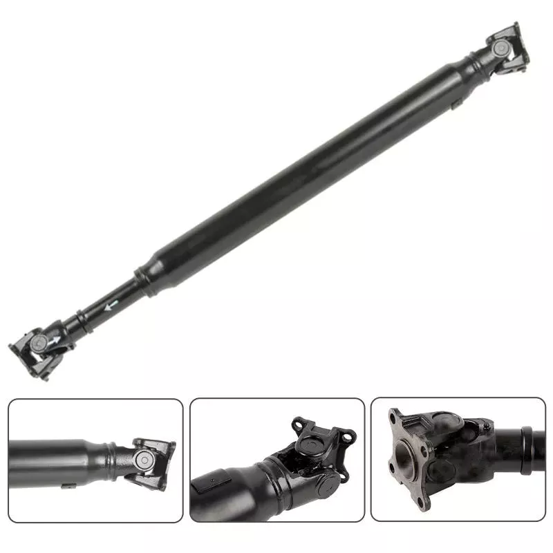
Are there any limitations or disadvantages associated with driveline systems?
While driveline systems offer numerous advantages in terms of power transmission and vehicle performance, there are also some limitations and disadvantages associated with their use. It’s important to consider these factors when designing, operating, and maintaining driveline systems. Let’s explore some of the limitations and disadvantages:
1. Complex Design and Integration:
Driveline systems can be complex in design, especially in modern vehicles with advanced technologies. They often consist of multiple components, such as transmissions, differentials, transfer cases, and drive shafts, which need to be properly integrated and synchronized. The complexity of the driveline system can increase manufacturing and assembly challenges, as well as the potential for compatibility issues or failures if not designed and integrated correctly.
2. Energy Losses:
Driveline systems can experience energy losses during power transmission. These losses occur due to factors such as friction, heat generation, mechanical inefficiencies, and fluid drag in components like gearboxes, differentials, and torque converters. The energy losses can negatively impact overall efficiency and result in reduced fuel economy or power output, especially in systems with multiple driveline components.
3. Limited Service Life and Maintenance Requirements:
Driveline components, like any mechanical system, have a limited service life and require regular maintenance. Components such as clutches, bearings, gears, and drive shafts are subject to wear and tear, and may need to be replaced or repaired over time. Regular maintenance, including lubrication, adjustments, and inspections, is necessary to ensure optimal performance and prevent premature failures. Failure to perform proper maintenance can lead to driveline malfunctions, increased downtime, and costly repairs.
4. Weight and Space Constraints:
Driveline systems add weight and occupy space within a vehicle. The additional weight affects fuel efficiency and overall vehicle performance. Moreover, the space occupied by driveline components can limit design flexibility, particularly in compact or electric vehicles where space optimization is crucial. Manufacturers must strike a balance between driveline performance, vehicle weight, and available space to meet the requirements of each specific vehicle type.
5. Noise, Vibration, and Harshness (NVH):
Driveline systems can generate noise, vibration, and harshness (NVH) during operation. Factors such as gear meshing, unbalanced rotating components, or improper driveline alignment can contribute to unwanted vibrations or noise. NVH issues can affect driving comfort, passenger experience, and vehicle refinement. Manufacturers employ various techniques, including vibration dampening materials, isolators, and precision engineering, to minimize NVH levels, but achieving complete elimination can be challenging.
6. Limited Torque Handling Capability:
Driveline systems have limitations in terms of torque handling capability. Excessive torque beyond the rated capacity of driveline components can lead to failures, such as shearing of gears, clutch slippage, or drive shaft breakage. High-performance vehicles or heavy-duty applications may require specialized driveline components capable of handling higher torque loads, which can increase costs and complexity.
7. Traction Limitations:
Driveline systems, particularly in vehicles with two-wheel drive configurations, may experience traction limitations, especially in slippery or off-road conditions. Power is typically transmitted to only one or two wheels, which can result in reduced traction and potential wheel slippage. This limitation can be mitigated by utilizing technologies such as limited-slip differentials, electronic traction control, or implementing all-wheel drive systems.
While driveline systems provide crucial power transmission and vehicle control, they do have limitations and disadvantages that need to be considered. Manufacturers, designers, and operators should carefully assess these factors and implement appropriate design, maintenance, and operational practices to optimize driveline performance, reliability, and overall vehicle functionality.
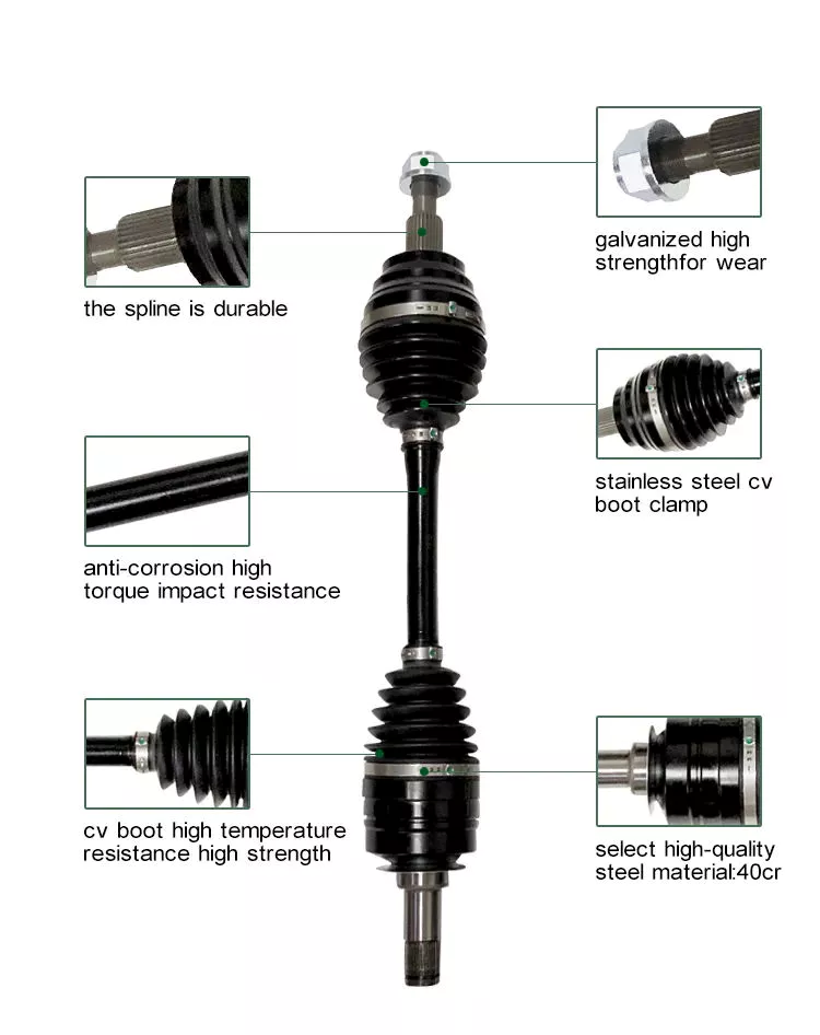
Can you explain the components of a typical driveline and their specific roles?
A typical driveline consists of several components that work together to transmit power from the engine or power source to the driven components, enabling motion and providing torque. Each component plays a specific role in the driveline system. Here’s an explanation of the key components of a typical driveline and their specific roles:
1. Engine: The engine is the power source of the driveline system. It converts fuel energy (such as gasoline or diesel) into mechanical power by the process of combustion. The engine generates rotational power, which is transferred to the driveline to initiate power transmission.
2. Transmission: The transmission is responsible for selecting the appropriate gear ratio and transmitting power from the engine to the driven components. It allows the driver or operator to control the speed and torque output of the driveline. In manual transmissions, the driver manually selects the gears, while in automatic transmissions, the gear shifts are controlled by the vehicle’s computer system.
3. Drive Shaft: The drive shaft, also known as a propeller shaft or prop shaft, is a tubular component that transmits rotational power from the transmission to the differential or the driven components. It typically consists of a hollow metal tube with universal joints at both ends to accommodate variations in driveline angles and allow for smooth power transfer.
4. Differential: The differential is a gearbox-like component that distributes power from the drive shaft to the wheels or driven axles while allowing them to rotate at different speeds, particularly during turns. It compensates for the difference in rotational speed between the inner and outer wheels in a turn, ensuring smooth and controlled operation of the driveline system.
5. Axles: Axles are shafts that connect the differential to the wheels. They transmit power from the differential to the wheels, allowing them to rotate and generate motion. In vehicles with independent suspension, each wheel typically has its own axle, while in solid axle configurations, a single axle connects both wheels on an axle assembly.
6. Clutch: In manual transmission systems, a clutch is employed to engage or disengage the engine’s power from the driveline. It allows the driver to smoothly engage the engine’s power to the transmission when shifting gears or coming to a stop. By disengaging the clutch, power transmission to the driveline is temporarily interrupted, enabling gear changes or vehicle stationary positions.
7. Torque Converter: Torque converters are used in automatic transmissions to transfer power from the engine to the transmission. They provide a fluid coupling between the engine and transmission, allowing for smooth power transmission and torque multiplication. The torque converter also provides a torque amplification effect, which helps in vehicle acceleration.
8. Universal Joints: Universal joints, also known as U-joints, are flexible couplings used in the driveline to accommodate variations in angles and misalignments between the components. They allow for the smooth transmission of power between the drive shaft and other components, compensating for changes in driveline angles during vehicle operation or suspension movement.
9. Constant Velocity Joints (CV Joints): CV joints are specialized joints used in some drivelines, particularly in front-wheel-drive and all-wheel-drive vehicles. They enable smooth power transmission while accommodating variations in angles and allowing the wheels to turn at different speeds. CV joints maintain a constant velocity during rotation, minimizing vibrations and power losses.
10. Transfer Case: A transfer case is a component found in four-wheel-drive and all-wheel-drive systems. It transfers power from the transmission to both the front and rear axles, allowing all wheels to receive power. The transfer case usually includes additional components such as a multi-speed gearbox and differential mechanisms to distribute power effectively to the axles.
These are the key components of a typical driveline and their specific roles. Each component is crucial in transferring power, enabling motion, and ensuring the smooth and efficient operation of vehicles and equipment.


editor by CX 2024-02-22