Mô tả
Powertrain Dynamics in Sprayer Applications
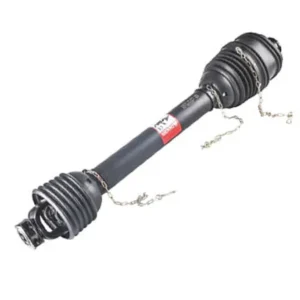
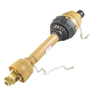
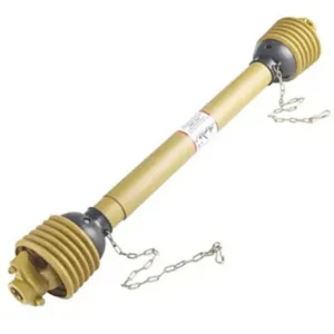
The pto shaft (Power Take-Off shaft) serves as the critical mechanical artery between a primary mover (such as a tractor) and secondary agricultural implements. In the specific context of Agricultural Sprayers—whether trailed, mounted, or self-propelled—the operational demands placed on the driveline are distinctively unforgiving. Unlike rotary tillers that experience constant soil impact, sprayers require absolute rotational consistency to drive high-capacity diaphragm pumps or centrifugal pumps.
The working principle involves transferring rotational kinetic energy from the tractor’s output spline (typically operating at 540 RPM or 1000 RPM) through a telescopic tubular shaft equipped with universal joints (U-joints) at both ends. This kinematic transfer must remain completely uninterrupted even as the tractor navigates uneven terrain, causing continuous fluctuations in the operational angle and the distance between the tractor and the sprayer.
For sprayer applications, any micro-fluctuations in PTO rpm directly translate to pressure drops in the fluid manifolds. This leads to uneven chemical atomization, resulting in compromised crop protection and significant chemical waste. EVER-POWER has specifically designed our agricultural sprayer driveline configurations to eliminate torsional vibration. By utilizing precision-forged yokes and dynamically balanced telescoping members, our systems maintain a continuous torque envelope, ensuring the spray nozzles receive uniform fluid pressure across hundreds of hectares.

Queensland Extreme Condition Field Study & Australian Compliance
Operating agricultural machinery in Australia introduces extreme environmental variables. In regions like Queensland and New South Wales, equipment is subjected to aggressive ultraviolet (UV) radiation, severe dust ingress, and vast field sizes that require machinery to run non-stop for 14 to 18 hours during peak application seasons.
Navigating WorkSafe Regulations and AS 1121.4 Standards
In the Australian agricultural sector, operator safety is heavily regulated. The Australian Standard AS 1121.4 (Agricultural tractor power take-off drive shafts and their guards) dictates stringent requirements for guarding mechanisms. A non-compliant or damaged guard is one of the leading causes of farm-related injuries and immediate machinery grounding by WorkSafe inspectors.
- Full Enclosure Mandate: Every tractor pto shaft supplied to the Australian market by EVER-POWER features a fully enclosed, non-rotating master shield. The internal bearings allow the shaft to rotate at 1000 RPM while the exterior plastic guard remains completely stationary when contacted.
- UV-Stabilized Polymers: Standard European or North American plastic guards often degrade and shatter within a single Australian summer. We utilize high-density polyethylene (HDPE) injected with advanced carbon-black UV stabilizers, extending the guard’s structural integrity to exceed 5 years under direct Queensland sunlight.
- Restraining Chains: In strict adherence to regional safety protocols, heavy-duty restraining chains are fitted at both ends with a tested tensile strength exceeding 450N, ensuring the guard cannot spin under heavy friction loads.
Engineer’s Field Notes: Overcoming Dynamic Load Failures
“During our 12 years of conducting failure analysis for broadacre farming operations in Western Australia and vineyard estates in Victoria, we identified a recurring catastrophic failure mode in sprayer drivelines. Standard U-joints were prematurely fracturing. Our metallurgical analysis revealed this wasn’t due to torque overload, but rather high-frequency torsional vibration caused by operating standard joints at angles exceeding 25 degrees during tight headland turns.”
“Based on this 10-year factory case data, EVER-POWER completely redesigned the articulation limits. For trailed sprayers that require zero-radius turns without disengaging the PTO, we implemented an 80-degree Constant Velocity (CV) joint on the tractor side. This kinematic compensation design eliminated the ‘galloping’ effect entirely, reducing pump bearing wear by 65%.”
Client Pain Point & Simulated Dialogue
Client in New South Wales (Broadacre Sprayer Operator): “Our current driveline cross-kits are failing every 100 hours. The dust is getting past the seals, scoring the needle bearings, and when we hit the headlands, the chatter from the shaft feels like it’s going to rip the diaphragm pump right off its mounts. It’s killing our maintenance budget and our uptime.”
EVER-POWER Solution: “We deployed our Series 6 Wide-Angle CV PTO shaft equipped with quad-lip Viton seals on the journals. By switching to this setup, the client completely neutralized the angular velocity fluctuations during 75-degree turns. Dust ingress was halted, and the maintenance interval was pushed from 50 hours to 250 hours. They reported zero driveline-related downtime for the entire chemical application season.”
Comprehensive Engineering Specifications (25-Point Data Set)
To facilitate exact engineering matching for your sprayer equipment, below is the detailed technical specification matrix of our heavy-duty sprayer-optimized shafts. Custom dimensional requirements can be accommodated through our OEM division.
| Parameter Description | Specification / Engineering Value |
|---|---|
| 1. Series Classification | Metric Series 4 / Series 6 (High-Torque) |
| 2. Power Rating @ 540 RPM | 35 HP (26 kW) to 64 HP (47 kW) |
| 3. Power Rating @ 1000 RPM | 54 HP (40 kW) to 100 HP (74 kW) |
| 4. Continuous Operating Torque | 460 Nm to 780 Nm |
| 5. Peak Torsional Yield Limit | 1850 Nm (Prior to mechanical deformation) |
| 6. Tractor Yoke Connection | 1-3/8″ 6-Spline or 1-3/8″ 21-Spline with Quick Disconnect Pin |
| 7. Implement Yoke Connection | 1-3/8″ 6-Spline with Overrunning Clutch or Shear Bolt |
| 8. Kinematic Articulation (Standard U-Joint) | Continuous 25° / Transient maximum 45° |
| 9. Kinematic Articulation (Wide Angle CV) | Continuous 50° / Transient maximum 80° |
| 10. Journal Cross Dimension (Series 4) | 27.0 mm x 74.6 mm |
| 11. Journal Cross Dimension (Series 6) | 30.2 mm x 92.0 mm |
| 12. Cross Material Metallurgy | 20CrMnTi Alloy Steel, Case Carburized |
| 13. Surface Hardness (Journals) | 58 – 62 HRC |
| 14. Case Depth (Carburization) | 1.2 mm to 1.5 mm |
| 15. Telescopic Tube Profile | Lemon Profile (European Std) or Triangular |
| 16. Inner Tube Wall Thickness | 3.2 mm / 4.0 mm (High tensile strength) |
| 17. Outer Tube Wall Thickness | 3.4 mm / 4.5 mm |
| 18. Minimum Closed Length (Lz) | 810 mm to 1210 mm (Customizable) |
| 19. Maximum Telescopic Stroke | 350 mm to 480 mm |
| 20. Dynamic Balancing Standard | ISO 1940 Grade G16 / G6.3 |
| 21. Guard Material Specification | HDPE with 15% Carbon-Black UV Inhibitor |
| 22. Bearing Seal Type | Quad-Lip Viton Elastomer (Dust & Moisture exclusion) |
| 23. Lubrication Interval | Extended 250 Hours (with specialized lithium-complex grease) |
| 24. Safety Certification standard | ISO 5673, AS 1121.4, CE Marked |
| 25. Operating Temperature Range | -30°C to +85°C |
| 26. Surface Anti-Corrosion Treatment | Cathodic Electrodeposition (E-coating) + Matte topcoat (>500h salt spray) |
| 27. Shear Bolt Torque Setting | M8 Grade 8.8 (approx. 1700 Nm shear limit) |
Evidence Density Injection: Performance Advantages over Inferior Alternatives
Instead of generalized claims of “high efficiency”, our engineering data provides concrete evidence of superiority when compared to standard aftermarket U-joints commonly imported into Australia without rigorous quality control.
- Thermal Dissipation: Standard cross kits utilizing basic lithium grease exhibit operating temperatures exceeding 90°C under 1000 RPM continuous loads, leading to accelerated grease liquefaction. Our proprietary journal micro-grooving and high-temperature synthetic grease maintain operational temperatures consistently at 65°C, ensuring a 300% longer bearing lifecycle.
- Torsional Rigidity: Standard seam-welded tubes demonstrate up to 4 degrees of torsional twist per meter under a 600 Nm load. Our seamless cold-drawn lemon profile tubes limit torsional deflection to less than 0.8 degrees per meter, preserving the precise timing required by advanced multi-cylinder diaphragm pumps.
- Dynamic Balance: An unbalanced shaft vibrating at 1000 RPM creates lateral forces exceeding 1500N on pump input bearings. By adhering to the G16 dynamic balancing protocol, our shafts reduce induced lateral bearing stress to below 120N.
Global Interoperability and Legal Compatibility Declarations
The global agricultural machinery landscape is heavily standardized, allowing for high-quality aftermarket components to seamlessly integrate with major original equipment manufacturers. We have meticulously mapped the geometric tolerances, spline configurations, and torque ratings to provide immediate drop-in replacements for existing sprayer fleets.
Whether your trailing sprayer relies on a metric Italian profile (triangular/lemon tubes) common in Bondioli & Pavesi configurations, or the German star-profile tubes utilized by Walterscheid, our inventory contains exact dimensional equivalents, ensuring zero modification is required during field installation.
International Field Case Studies
1. Victoria, Australia (Vineyards)
Application: Narrow-track Orchard Sprayer.
Challenge: Extremely tight headland turns causing U-joint binding.
Result: Implementing a 1-3/8″ 6-spline CV joint shaft allowed the operator to maintain 540 RPM through 70-degree turns. The client evaluated a 15% reduction in turning time and eliminated pump seal blowouts previously caused by RPM surging.
2. California, USA (Almond Orchards)
Application: High-Volume Air Blast Sprayer.
Challenge: Heavy dust environments destroying standard bearings within weeks.
Result: Installed Series 6 heavy-duty shaft with quad-lip Viton seals. The customized sealing technology excluded fine silica dust, extending the operational life of the cross kits from 150 hours to over 600 hours before requiring replacement.
3. Veneto, Italy (Viticulture)
Application: Multi-row Trailed Sprayer.
Challenge: High impact loads when activating the massive rear fan assembly.
Result: Integrated a frictional slip clutch on the implement yoke. When the fan inertia exceeded safe limits during start-up, the clutch slipped precisely at 1200 Nm, protecting both the tractor PTO stub and the sprayer’s internal gearbox from shear forces.
Powertrain Selection Essentials: Precision Matching Protocol
Selecting the correct PTO driveline requires precise mathematical and geometrical evaluations to prevent disastrous mechanical failures. Utilizing our powertrain selection essentials ensures maximum power transfer efficiency and uncompromising safety.
| Step 1: Power & Torque Profiling | Determine the tractor’s horsepower at the PTO stub (e.g., 60 HP) and the nominal operating RPM (540 or 1000). Always apply a Service Factor of 1.5 for agricultural sprayers due to the high startup inertia of large centrifugal fans or the pulsing nature of multi-diaphragm pumps. |
| Step 2: Spline Identification | Measure the output shaft on the tractor and the input shaft on the sprayer. Standard European and Australian tractors primarily utilize 1-3/8″ 6-spline for 540 RPM, and 1-3/8″ 21-spline for 1000 RPM. Verify if the sprayer side requires a smooth bore with a keyway or a splined connection. |
| Step 3: Dimensional Calculation (Lz) | Position the tractor and the sprayer on level ground in a straight line. Measure the distance from the tip of the tractor spline to the tip of the implement spline. The chosen shaft must allow for at least 33% tube overlap at maximum extension, and must not bottom out (minimum 25mm clearance) during the tightest turning radius. |
| Step 4: Safety Device Specification | Sprayers are susceptible to pump blockages. Specify a shear bolt clutch for basic overload protection, or an overrunning clutch (freewheel) if the sprayer possesses a massive rear fan, which prevents the fan’s inertia from pushing the tractor forward when the PTO is disengaged. |
Targeted Installation Steps for Sprayer Applications
- Surface Preparation: Vigorously clean both the tractor and implement spline shafts using a steel brush and appropriate solvent to remove rust and debris. Apply a thin film of lithium grease to facilitate smooth sliding.
- Directional Orientation verification: PTO drive shafts are directional. Locate the tractor icon imprinted on the plastic guard. The end featuring the overload protection device (clutch/shear bolt) must be installed on the implement (sprayer) side.
- Locking Mechanism Engagement: Depress the quick-disconnect pin completely, slide the yoke onto the spline, and release the pin. Vigorously pull the shaft backward to ensure the locking pin has firmly seated into the annular groove of the spline shaft.
- Guard Restraint Anchoring: Attach the safety chains to non-rotating structural points on both the tractor and the sprayer. Allow sufficient slack to permit the full range of articulation during cornering, ensuring the chain cannot wrap around the spinning tube.
Driveline Troubleshooting & Fault Diagnosis
Fault Signature: Severe Vibration and Knocking Sounds During Turns
Engineering Diagnosis: This indicates severe kinematic inequality. The U-joints are operating at angles exceeding their design limit (typically > 25°), causing non-constant velocity transmission. Alternatively, the internal telescopic tubes lack sufficient overlap, causing the shaft to bow under torsional load.
Corrective Action: Verify the geometry between the tractor drawbar and the implement input shaft. Ensure the joint angles are equal. If tight turns are structurally mandatory for the field layout, the assembly must be upgraded to a Wide-Angle CV joint configuration.
Fault Signature: Implement Fails to Rotate / Frequent Shear Bolt Fractures
Engineering Diagnosis: Continuous shear bolt fracture suggests either the diaphragm pump is experiencing hydraulic locking, the fan assembly is obstructed, or the operator is engaging the PTO clutch at excessive engine RPM.
Corrective Action: Never replace a shear bolt with a higher-grade steel bolt, as this destroys the safety mechanism and will lead to catastrophic gearbox failure. Engage the PTO at the lowest possible engine idle before ramping up to operational RPM. Inspect the pump for internal blockages.
Frequently Asked Questions (FAQ)
Q1: Can I manually cut the PTO shaft to fit my specific sprayer geometry?
Yes, custom sizing in the field is a standard procedure. To shorten the driveline, separate the two halves. You must cut exactly the same length from both the internal metal tubes and the external plastic guard tubes. After cutting, it is critical to use a semi-round file to carefully deburr all metal edges. Failure to deburr will cause the metal shavings to score the opposing tube, resulting in the shaft binding during compression.
Q2: Why does my orchard sprayer specifically require an overrunning clutch?
Orchard and vineyard sprayers typically utilize massive rear fan assemblies to generate air-blast dispersion. These heavy metal or composite fans store immense kinetic energy. When you suddenly disengage the tractor’s PTO or rapidly decelerate, the fan’s inertia attempts to continue spinning the driveline. Without an overrunning clutch (which acts like a bicycle freewheel), this stored energy will back-drive through the shaft into the tractor transmission, potentially causing the tractor to lurch forward dangerously.
Q3: How often should I lubricate the universal joints in dusty Australian conditions?
While standard international manuals suggest lubrication every 50 operating hours, the extreme silica dust and high temperatures of the Australian outback alter this paradigm. For severe conditions, we recommend purging the cross journals with high-temperature, lithium-complex grease every 20-25 hours. Pump the grease gun until clean grease visibly purges from all four seals. The telescoping tubes must be separated and the internal profiles heavily smeared with grease at the beginning of every season.
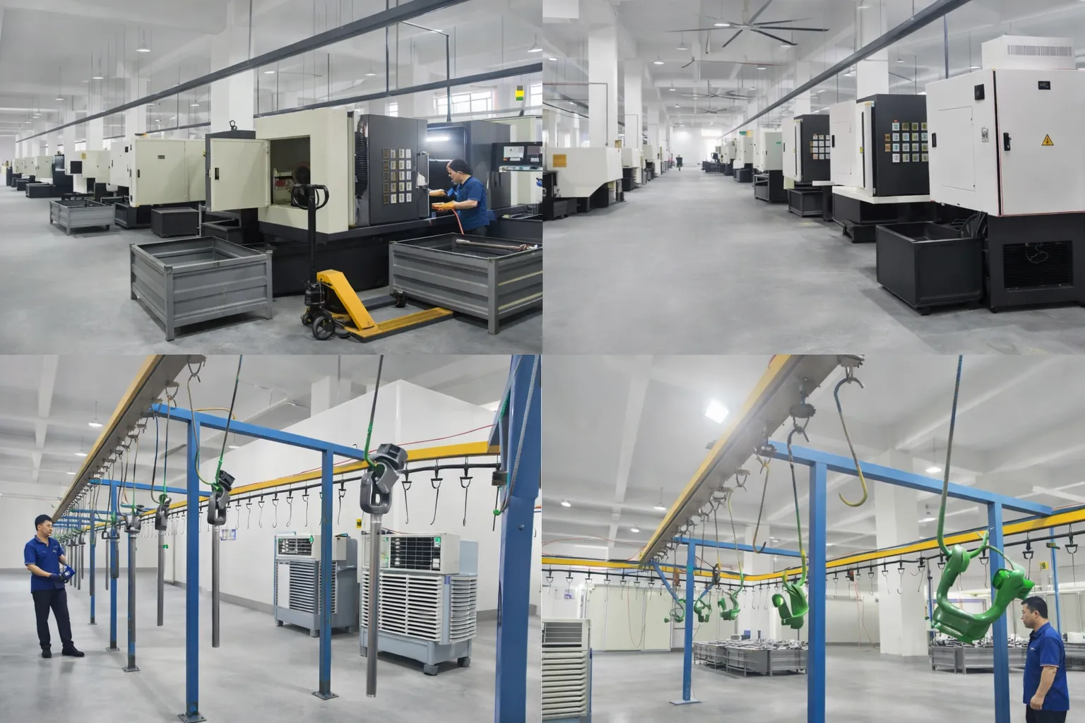
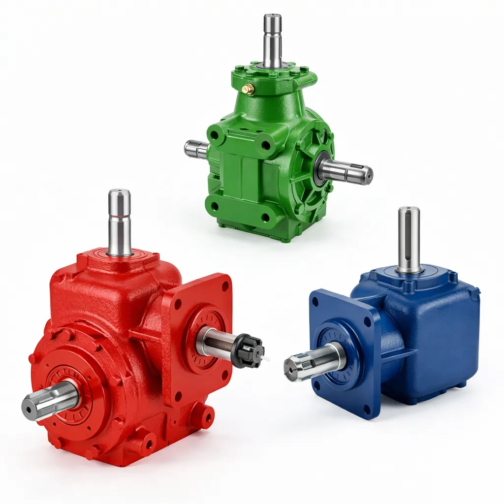
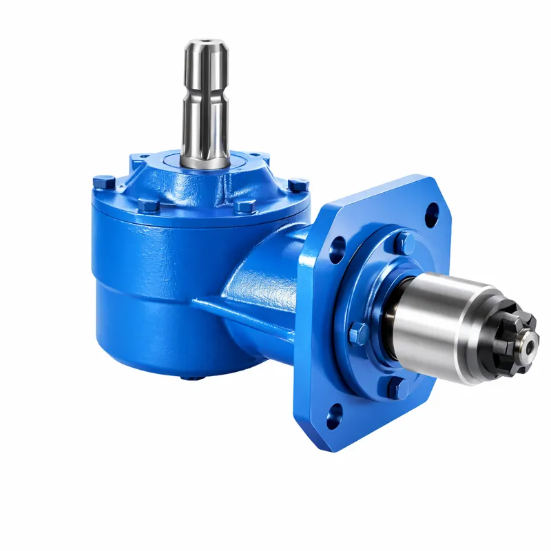
Synergistic Power Transfer: Advanced Agricultural Gearboxes
The power transmission journey does not terminate at the end of the shaft. To establish a flawless, highly efficient mechanical ecosystem, the kinetic energy must be seamlessly transferred into an agricultural gearbox. EVER-POWER designs and manufactures a premium portfolio of precision gearboxes that are perfectly matched to the torque output and spline configurations of our driveline systems.
Comprehensive Driveline Component Ecosystem
EVER-POWER is not merely an assembly plant; we are a foundational manufacturer of the entire power transmission matrix. Our ecosystem extends to vital secondary components designed with the identical rigorous quality control as our primary assemblies.
Precision Sprockets
Manufactured using CNC hobbing machines and subjected to high-frequency induction hardening on the tooth profiles. Ideal for planter metering mechanisms and chain-driven agitators.
V-Belt Pulleys
Cast from high-grade GG25 cast iron and dynamically balanced to G6.3 specifications. They prevent high-frequency belt vibration in high-speed fan drive applications.
Industrial Roller Chains
Featuring shot-peened side plates and pre-stretched assembly limits, our chains offer exceptional tensile strength and resistance to elongation under heavy loads.
Forged Spline Shafts
Custom fabricated input and output stub shafts for gearboxes, providing exact 6-spline or 21-spline profiles with zero-tolerance engagement to prevent fretting corrosion.

Empower Your Agricultural Fleet with Uncompromising Engineering
As a premier global manufacturer with formidable internal R&D capabilities, EVER-POWER goes far beyond off-the-shelf components. We possess the metallurgical expertise and CNC manufacturing bandwidth to produce highly specialized, non-standard driveline and gearbox solutions tailored precisely to your mechanical blueprints, spatial constraints, and extreme environmental requirements.
We welcome technical drawings and sample-based customizations from agricultural OEMs, wholesale distributors, and massive-scale farming enterprises globally.
Email directly at: [email protected]