Product Description
Company Profile
Established in 2009, HangZhou CZPT Trading Co., Ltd is a professional supplier for conveyor parts, located in ZHangZhoug province. We focus on supplying a variety of conveyor parts, including conveyor tubes, conveyor frames, conveyor rollers, bearing housings and so forth.
With our professional technology R&D team, and experienced quality control department, our products have been awarded the ISO9001 Quality Management System Standard and our main markets are in America, Europe, Asia and Australia.
|
Factory advantage |
Professional and experienced technology team | ||
| All products inspected before shipping with reasonable prices | |||
| Low MOQ and free sample | |||
| We are audited by SGS and passed the ISO9001:2008 certification | |||
|
Industries service |
Industrial machine | ||
| Electronic and communication | |||
| Oil, gas,mining and petroleum | |||
| Construction industry | |||
| Equipment | CNC Machining Center, CNC Lathes, CNC Milling Machines, Punching and drilling machines, Stamping machines | ||
| Precision Processing | CNC machining, CNC turning and milling, laser cutting, drilling, grinding, bending, stamping, welding | ||
Roller size
| No. | Standard Diameter | Length Range (mm) |
Bearing Type Min-Max |
Shell Thickness of Roller | |
| mm | Inch | ||||
| 1 | 63.5 | 2 1/2 | 150-3500 | 203 204 | 3.0mm-4.0mm |
| 2 | 76 | 3 | 150-3500 | 204 | 3.0mm-4.5mm |
| 3 | 89 | 3 1/3 | 150-3500 | 204 205 | 3.0mm-4.5mm |
| 4 | 102 | 4 | 150-3500 | 3.2mm-4.5mm | |
| 5 | 108 | 4 1/4 | 150-3500 | 306 | 3.5mm-4.5mm |
| 6 | 114 | 4 1/2 | 150-3500 | 306 | 3.5mm-4.5mm |
| 7 | 127 | 5 | 150-3500 | 306 | 3.5mm-5.0mm |
| 8 | 133 | 5 1/4 | 150-3500 | 305 306 | 3.5mm-5.0mm |
| 9 | 140 | 5 1/2 | 150-3500 | 306 307 | 3.5mm-5.0mm |
| 10 | 152 | 6 | 150-3500 | 4.0mm-5.0mm | |
| 11 | 159 | 6 1/4 | 150-3500 | 4.0mm-5.0mm | |
| 12 | 165 | 6 1/2 | 150-3500 | 307 308 | 4.5mm-6.0mm |
| 13 | 177.8 | 7 | 150-3500 | 309 | 4.5mm-6.0mm |
| 14 | 190.7 | 7 1/2 | 150-3500 | 309 310 | 4.5mm-7.0mm |
| 15 | 194 | 7 5/8 | 150-3500 | 309 310 | 4.5mm-8.0mm |
| 16 | 219 | 8 5/8 | 150-3500 | 4.5mm-8.0mm | |
Advantage:
1.The life time: More than 50000 hours
2. TIR (Total Indicator Runout)
0.5mm (0.0197″) for Roll Length 0-600mm
0.8mm (0.571″) for Roll Length 601-1350mm
1.0mm (0. 0571 “) for Roll Length over 1350mm
3.Shaft Float≤0.8mm
4..Samples for testing are available.
5. Lower resistance
6. Small maintain work
7. High load capability
8. Dust proof & water proof
CONVRYOR ROLLER SHAFTS
| We can produce roller shafts and We do customeized |
| Product Size:φ10mm – 70mm |
| Max Length: 3000mm |
| Surface Tolerance: g6 |
| Surface Roughness:0.8mm |
| Specification | ASTM A108 AS1443 |
| Steel Grade | Q235B,C1571,C1045(we can also do other steel grade per your requirments) |
| Size | Φ18mm-φ62mm |
| Diameter Tolerance | ISO286-2,H7/H8 |
| Straightness | 2000:1 |
| O.D | 63.5-219.1mm |
| W .T | 0.45-20mm |
| Length | 6–12m |
| Standard | SANS 657/3,ASTM 513,AS 1163,BS6323,EN10305 |
| Material | Q235B, S355,S230,C350,E235 etc. |
| Technique | Welded,Seamless |
| Surface | oiled ,galvanized or painted with all kinds of colors according to client’s request. |
| Ends | 1.Plain ends, |
| 2.Threading at both side with plastice caps | |
| 3.Threading at both side with socket/coupling. | |
| 4.Beveled ends, and so on | |
| Packing | 1.Water-proof plastic cloth, |
| 2.Woven bags, | |
| 3.PVC package, | |
| 4.Steel strips in bundles | |
| 5.As your requirment | |
| Usage | 1.For low pressure liquid delivery such as water,gas and oil. |
| 2.For construction | |
| 3.Mechanical equipment | |
| 4.For Furniture | |
| Payment&Trade Terms | 1.Payment : T/T,L/C, D/P, Western union |
| 2.Trade Terms:FOB/CFR/CIF | |
| 3.Minimum quantity of order : 10 MT (10,000KGS) | |
| Delivery Time | 1.Usually,within10-20days after receiving your down payment. |
| 2.According to the order quantity |
Conveyor Roller Tube
|
Conveyor Roller Tube |
Specification | SANS657/3,ASTM513,AS1163,BS6323,EN10305 or equivalent international standard. |
| Steel grade | S355/S230,C350,E235,Q235B | |
| Sizes | 63.5mm-219.1mm ect | |
| Ovality tolerance of body | ≤0.4mm(60.3mm-152.4mm) | |
| ≤0.5mm(159MM-168.3mm) | ||
| ≤0.6mm(178mm-219mm) | ||
| Straightness | 2000:1 |
if you are interesting in our products or want any further information, please feel free to contact us!
I am looking CZPT to your reply.
Best regards
Ruth
HangZhou CZPT TRADING CO., LTD
1801 CZPT Building, No.268 Xierhuan Road, HangZhou City, ZHangZhoug Province, China
| Steel Grade: | C1018 C1020 |
|---|---|
| Standard: | ASTM A108 |
| Size: | Od18mm—62mm |
| Surface Tolerance: | G6 |
| Max Length: | Max 3000mm |
| Surface Roughness: | 0.8 |
| Samples: |
US$ 0/Piece
1 Piece(Min.Order) | |
|---|
| Customization: |
Available
| Customized Request |
|---|
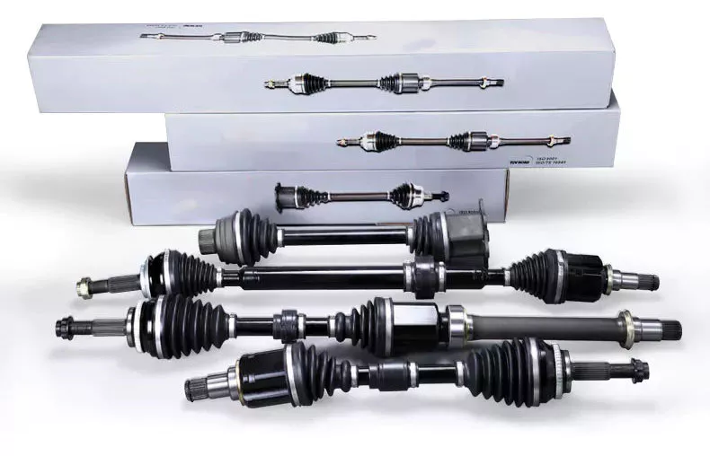
How do drivelines ensure optimal power transfer while minimizing energy losses?
Drivelines play a crucial role in ensuring optimal power transfer from the engine to the wheels while minimizing energy losses. The design and components of the driveline system are carefully engineered to maximize efficiency and minimize power wastage. Here are some key factors that contribute to achieving optimal power transfer and minimizing energy losses within a driveline:
1. Efficient Power Transmission:
Drivelines utilize various components, such as transmissions, clutches, and torque converters, to transmit power from the engine to the wheels. These components are designed to minimize energy losses by reducing friction, improving gear mesh efficiency, and optimizing torque transfer. For example, using low-friction materials, such as roller bearings, and employing advanced gear designs, like helical or hypoid gears, can help reduce power losses due to friction and gear meshing.
2. Gear Ratio Optimization:
The selection of appropriate gear ratios is essential for achieving optimal power transfer. By choosing gear ratios that match the engine’s power characteristics and the vehicle’s driving conditions, the driveline can efficiently convert and transmit power to the wheels. Optimized gear ratios ensure that the engine operates within its optimal RPM range, reducing unnecessary power losses and improving overall efficiency.
3. Limited Slip Differentials:
In driveline systems with multiple driven wheels (such as all-wheel drive or four-wheel drive), limited slip differentials (LSDs) are often employed to distribute power between the wheels. LSDs allow for better traction by transferring torque to the wheels with more grip while minimizing energy losses. By allowing some degree of differential wheel speed, LSDs ensure power is efficiently transmitted to the wheels that can utilize it most effectively.
4. Hybrid and Electric Drivetrains:
In hybrid and electric drivetrains, driveline systems are designed to optimize power transfer and minimize energy losses specific to the characteristics of electric motors and energy storage systems. These drivetrains often utilize sophisticated power electronics, regenerative braking systems, and advanced control algorithms to efficiently manage power flow and energy regeneration, resulting in improved overall system efficiency.
5. Aerodynamic Considerations:
Drivelines can also contribute to optimal power transfer by considering aerodynamic factors. By minimizing air resistance through streamlined vehicle designs, efficient cooling systems, and appropriate underbody airflow management, drivelines help reduce the power required to overcome aerodynamic drag. This, in turn, improves overall driveline efficiency and minimizes energy losses.
6. Advanced Control Systems:
The integration of advanced control systems within drivelines allows for optimized power transfer and efficient operation. Electronic control units (ECUs) monitor various parameters such as throttle position, vehicle speed, and driving conditions to adjust power distribution, manage gear shifts, and optimize torque delivery. By continuously adapting to real-time conditions, these control systems help maximize power transfer efficiency and minimize energy losses.
7. Material Selection and Weight Reduction:
The choice of materials and weight reduction strategies in driveline components contribute to minimizing energy losses. Lightweight materials, such as aluminum or composites, reduce the overall weight of the driveline system, resulting in reduced inertia and lower power requirements. Additionally, reducing the weight of rotating components, such as driveshafts or flywheels, helps improve driveline efficiency by minimizing energy losses associated with rotational inertia.
8. Regular Maintenance and Lubrication:
Proper maintenance and lubrication of driveline components are essential for minimizing energy losses. Regular maintenance ensures that driveline components, such as bearings and gears, are in optimal condition, minimizing frictional losses. Additionally, using high-quality lubricants and maintaining appropriate lubrication levels reduces friction and wear, improving driveline efficiency.
By incorporating these design considerations and engineering techniques, drivelines can achieve optimal power transfer while minimizing energy losses. This leads to improved overall efficiency, enhanced fuel economy, and reduced environmental impact.
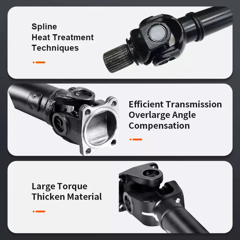
What safety precautions should be followed when working with driveline components?
Working with driveline components requires careful attention to safety to prevent accidents, injuries, and damage to equipment. Driveline components, such as transmissions, drive shafts, and differentials, can involve rotating parts, high torque, and heavy machinery, making it essential to follow proper safety precautions. Here are some important safety measures to consider when working with driveline components:
1. Personal Protective Equipment (PPE):
Always wear appropriate personal protective equipment, including safety glasses, gloves, and protective clothing. PPE helps protect against potential hazards such as flying debris, sharp edges, and contact with hot or moving parts. Use steel-toed safety boots to protect your feet from heavy objects or accidental impacts.
2. Lockout/Tagout:
Prior to working on driveline components, follow lockout/tagout procedures to ensure the equipment is properly shut down and isolated from its power source. Lockout/tagout involves disconnecting power, applying locks or tags to control switches, and verifying that the equipment is de-energized. This prevents accidental startup or release of stored energy that could cause serious injuries.
3. Vehicle/Equipment Stability:
Ensure that the vehicle or equipment is stable and securely supported before working on driveline components. Use appropriate jack stands or hoists to provide a stable and reliable support structure. Never rely solely on hydraulic jacks or unstable supports, as they can lead to accidents or equipment damage.
4. Proper Lifting Techniques:
When handling heavy driveline components, use proper lifting techniques to prevent strains or injuries. Lift with your legs, not your back, and get assistance when dealing with heavy or bulky components. Use mechanical lifting aids, such as hoists or cranes, when necessary to avoid overexertion or dropping components.
5. Component Inspection:
Prior to installation or maintenance, carefully inspect driveline components for any signs of damage, wear, or corrosion. Replace any worn or damaged parts to ensure safe and reliable operation. Follow the manufacturer’s guidelines and specifications for component inspection, maintenance, and replacement intervals.
6. Proper Tools and Equipment:
Use the correct tools and equipment for the job. Improper tools or makeshift solutions can lead to accidents, damaged components, or stripped fasteners. Follow the manufacturer’s recommendations for specialized tools or equipment needed for specific driveline components.
7. Follow Service Manuals and Procedures:
Refer to the relevant service manuals and follow proper procedures when working on driveline components. Service manuals provide step-by-step instructions, torque specifications, and safety precautions specific to the vehicle or equipment you are working on. Adhering to these guidelines ensures proper disassembly, installation, and adjustment of driveline components.
8. Proper Disposal of Fluids and Waste:
Dispose of fluids, such as oil or coolant, and waste materials in accordance with local regulations. Spilled fluids can create slip hazards, and improper disposal can harm the environment. Use appropriate containers and disposal methods as prescribed by local laws and regulations.
9. Training and Knowledge:
Ensure that individuals working with driveline components have received proper training and possess the necessary knowledge and skills. Inadequate training or lack of knowledge can lead to errors, accidents, or improper installation, compromising safety and performance.
10. Follow Workplace Safety Regulations:
Adhere to workplace safety regulations and guidelines established by relevant authorities. These regulations may include specific requirements for working with driveline components, such as safety standards, training requirements, and equipment certifications. Stay updated on safety regulations and ensure compliance to maintain a safe working environment.
By following these safety precautions, individuals can minimize the risk of accidents, injuries, and equipment damage when working with driveline components. Safety should always be a top priority to promote a secure and productive work environment.

What is a driveline and how does it function in vehicles and machinery?
A driveline, also known as a drivetrain, refers to the components and systems responsible for transmitting power from the engine to the wheels or tracks in vehicles and machinery. It encompasses various elements such as the engine, transmission, drive shafts, differentials, axles, and wheels or tracks. The driveline plays a crucial role in converting the engine’s power into motion and enabling the vehicle or machinery to move. Here’s a detailed explanation of how the driveline functions in vehicles and machinery:
1. Power Generation: The driveline starts with the engine, which generates power by burning fuel or utilizing alternative energy sources. The engine produces rotational force, known as torque, which is transferred to the driveline for further transmission to the wheels or tracks.
2. Transmission: The transmission is a crucial component of the driveline that controls the distribution of power and torque from the engine to the wheels or tracks. It allows the driver or operator to select different gear ratios to optimize performance and efficiency based on the vehicle’s speed and load conditions. The transmission can be manual, automatic, or a combination of both, depending on the specific vehicle or machinery.
3. Drive Shaft: The drive shaft, also called a propeller shaft, is a rotating mechanical component that transmits torque from the transmission to the wheels or tracks. In vehicles with rear-wheel drive or four-wheel drive, the drive shaft transfers power to the rear axle or all four wheels. In machinery, the drive shaft may transfer power to the tracks or other driven components. The drive shaft is typically a tubular metal shaft with universal joints at each end to accommodate the movement and misalignment between the transmission and the wheels or tracks.
4. Differential: The differential is a device located in the driveline that enables the wheels or tracks to rotate at different speeds while still receiving power. It allows the vehicle or machinery to smoothly negotiate turns without wheel slippage or binding. The differential consists of a set of gears that distribute torque between the wheels or tracks based on their rotational requirements. In vehicles with multiple axles, there may be differentials on each axle to provide power distribution and torque balancing.
5. Axles: Axles are shafts that connect the differential to the wheels or tracks. They transmit torque from the differential to the individual wheels or tracks, allowing them to rotate and propel the vehicle or machinery. Axles are designed to withstand the loads and stresses associated with power transmission and wheel movement. They may be solid or independent, depending on the vehicle or machinery’s suspension and drivetrain configuration.
6. Wheels or Tracks: The driveline’s final components are the wheels or tracks, which directly contact the ground and provide traction and propulsion. In vehicles with wheels, the driveline transfers power from the engine to the wheels, allowing them to rotate and propel the vehicle forward or backward. In machinery with tracks, the driveline transfers power to the tracks, enabling the machinery to move over various terrains and surfaces.
7. Functioning: The driveline functions by transmitting power from the engine through the transmission, drive shaft, differential, axles, and finally to the wheels or tracks. As the engine generates torque, it is transferred through the transmission, which selects the appropriate gear ratio based on the vehicle’s speed and load. The drive shaft then transfers the torque to the differential, which distributes it between the wheels or tracks according to their rotational requirements. The axles transmit the torque from the differential to the individual wheels or tracks, allowing them to rotate and propel the vehicle or machinery.
8. Four-Wheel Drive and All-Wheel Drive: Some vehicles and machinery are equipped with four-wheel drive (4WD) or all-wheel drive (AWD) systems, which provide power to all four wheels simultaneously. In these systems, the driveline includes additional components such as transfer cases and secondary differentials to distribute power to the front and rear axles. The driveline functions similarly in 4WD and AWD systems, but with enhanced traction and off-road capabilities.
In summary, the driveline is a vital component in vehicles and machinery, responsible for transmitting power from the engine to the wheels or tracks. It involves the engine, transmission, drive shafts, differentials, axles, and wheels or tracks. By efficiently transferring torque and power, the driveline enables vehicles and machinery to move, providing traction, propulsion, and control. The specific configuration and components of the driveline may vary depending on the vehicle or machinery’s design, purpose, and drive system.


editor by CX 2023-10-31