คำอธิบายผลิตภัณฑ์
คำอธิบายผลิตภัณฑ์
SWC BH Cardan Shaft Basic Parameter And Main Dimension
Cardan shaft is widely used in rolling mill, punch, straightener, crusher, ship drive, paper making equipment, common machinery, water pump equipment, test bench, and other mechanical applications.
Advantage:
1. Low life-cycle costs and long service life;
2. Increase productivity;
3. Professional and innovative solutions;
4. Reduce carbon dioxide emissions, and environmental protection;
5. High torque capacity even at large deflection angles;
6. Easy to move and run smoothly;
Detailed Photos
Product Parameters
| Model | Tn kN • m |
T. |
p (.) |
LS mm |
Lmin | ขนาด mm |
I kg. m2 | m kg |
|||||||||||
| Di js11 |
d2 H7 |
Da | Lm | n-d | k | t | b h9 |
g | Lmin | 100mm | Lmin | 100mm | |||||||
| SWC58BH | 58 | 0.15 | 0.075 | ≤22 | 35 | 325 | 47 | 30 | 38 | 35 | 4-5 | 3.5 | 1.5 | – | – | – | – | 2.2 | – |
| SWC65BH | 65 | 0.25 | 0.125 | ≤22 | 40 | 360 | 52 | 35 | 42 | 46 | 4-6 | 4.5 | 1.7 | – | – | – | – | 3.0 | – |
| SWC75BH | 75 | 0.50 | 0.25 | ≤22 | 40 | 395 | 62 | 42 | 50 | 58 | 6-6 | 5.5 | 2.0 | – | – | – | – | 5.0 | – |
| SWC90BH | 90 | 1.0 | 0.50 | ≤22 | 45 | 435 | 74.5 | 47 | 54 | 58 | 4-8 | 6.0 | 2.5 | – | – | – | – | 6.6 | – |
| SWC100BH | 100 | 1.5 | 0.75 | ≤25 | 55 | 390 | 84 | 57 | 60 | 58 | 6-9 | 7 | 2.5 | – | – | 0.0044 | 0.00019 | 6.1 | 0.35 |
| SWC120BH | 120 | 2.5 | 1.25 | ≤25 | 80 | 485 | 102 | 75 | 70 | 68 | 8-11 | 8 | 2.5 | – | – | 0.5719 | 0.00044 | 10.8 | 0.55 |
| SWC150BH | 150 | 5 | 2.5 | ≤25 | 80 | 590 | 13.0 | 90 | 89 | 80 | 8-13 | 10 | 3.0 | – | – | 0.0423 | 0.00157 | 24.5 | 0.85 |
| SWC160BH | 160 | 10 | 5 | ≤25 | 80 | 660 | 137 | 100 | 95 | 110 | 8-15 | 15 | 3.0 | 20 | 12 | 0.1450 | 0.0060 | 68 | 1.72 |
| SWC180BH | 180 | 20 | 10 | ≤25 | 100 | 810 | 155 | 105 | 114 | 130 | 8-17 | 17 | 5.0 | 24 | 14 | 0.1750 | 0.0070 | 70 | 2.8 |
| SWC200BH | 200 | 32 | 16 | ≤15 | 110 | 860 | 170 | 120 | 127 | 135 | 8-17 | 19 | 5.0 | 28 | 16 | 0.3100 | 0.0130 | 86 | 3.6 |
| SWC225BH | 225 | 40 | 20 | ≤15 | 140 | 920 | 196 | 135 | 152 | 120 | 8-17 | 20 | 5.0 | 32 | 9.0 | 0.5380 | 0.5714 | 122 | 4.9 |
| SWC250BH | 250 | 63 | 31.5 | ≤15 | 140 | 1035 | 218 | 150 | 168 | 140 | 8-19 | 25 | 6.0 | 40 | 12.5 | 0.9660 | 0.5717 | 172 | 5.3 |
| SWC285BH | 285 | 90 | 45 | ≤15 | 140 | 1190 | 245 | 170 | 194 | 160 | 8-21 | 27 | 7.0 | 40 | 15.0 | 2.0110 | 0.571 | 263 | 6.3 |
| SWC315BH | 315 | 125 | 63 | ≤15 | 140 | 1315 | 280 | 185 | 219 | 180 | 10-23 | 32 | 8.0 | 40 | 15.0 | 3.6050 | 0.571 | 382 | 8.0 |
| SWC350BH | 350 | 180 | 90 | ≤15 | 150 | 1410 | 310 | 210 | 267 | 194 | 10-23 | 35 | 8.0 | 50 | 16.0 | 7.571 | 0.2219 | 582 | 15.0 |
| SWC390BH | 390 | 250 | 125 | ≤15 | 170 | 1590 | 345 | 235 | 267 | 215 | 10-25 | 40 | 8.0 | 70 | 18.0 | 12.164 | 0.2219 | 738 | 15.0 |
| SWC440BH | 440 | 355 | 180 | ≤15 | 190 | 1875 | 390 | 255 | 325 | 260 | 16-28 | 42 | 10 | 80 | 20.0 | 21.420 | 0.4744 | 1190 | 21.7 |
| SWC490BH | 490 | 500 | 250 | ≤15 | 190 | 1985 | 435 | 275 | 325 | 270 | 16-31 | 47 | 12 | 90 | 22.5 | 32.860 | 0.4744 | 1452 | 21.7 |
| SWC550BH | 550 | 710 | 355 | ≤15 | 240 | 2300 | 492 | 320 | 426 | 305 | 16-31 | 50 | 12 | 100 | 22.5 | 68.920 | 1.3570 | 2380 | 34 |
Packaging & Shipping
Company Profile
HangZhou CZPT Machinery Manufacturing Co., Ltd. is a high-tech enterprise specializing in the design and manufacture of various types of coupling. There are 86 employees in our company, including 2 senior engineers and no fewer than 20 mechanical design and manufacture, heat treatment, welding, and other professionals.
Advanced and reasonable process, complete detection means. Our company actively introduces foreign advanced technology and equipment, on the basis of the condition, we make full use of the advantage and do more research and innovation. Strict to high quality and operate strictly in accordance with the ISO9000 quality certification system standard mode.
Our company supplies different kinds of products. High quality and reasonable price. We stick to the principle of “quality first, service first, continuous improvement and innovation to meet the customers” for the management and “zero defect, zero complaints” as the quality objective.
Our Services
1. Design Services
Our design team has experience in Cardan shafts relating to product design and development. If you have any needs for your new product or wish to make further improvements, we are here to offer our support.
2. Product Services
raw materials → Cutting → Forging →Rough machining →Shot blasting →Heat treatment →Testing →Fashioning →Cleaning→ Assembly→Packing→Shipping
3. Samples Procedure
We could develop the sample according to your requirement and amend the sample constantly to meet your need.
4. Research & Development
We usually research the new needs of the market and develop new models when there are new cars in the market.
5. Quality Control
Every step should be a particular test by Professional Staff according to the standard of ISO9001 and TS16949.
FAQ
Q 1: Are you a trading company or a manufacturer?
A: We are a professional manufacturer specializing in manufacturing
various series of couplings.
Q 2:Can you do OEM?
Yes, we can. We can do OEM & ODM for all customers with customized PDF or AI format artwork.
Q 3:How long is your delivery time?
Generally, it is 20-30 days if the goods are not in stock. It is according to quantity.
Q 4: Do you provide samples? Is it free or extra?
Yes, we could offer the sample but not for free. Actually, we have an excellent price principle, when you make the bulk order the cost of the sample will be deducted.
Q 5: How long is your warranty?
A: Our Warranty is 12 months under normal circumstances.
Q 6: What is the MOQ?
A: Usually our MOQ is 1pcs.
Q 7: Do you have inspection procedures for coupling?
A:100% self-inspection before packing.
Q 8: Can I have a visit to your factory before the order?
A: Sure, welcome to visit our factory.
Q 9: What’s your payment?
A:1) T/T.
♦Contact Us
Web: huadingcoupling
Add: No.11 HangZhou Road,Chengnan park,HangZhou City,ZheJiang Province,China
/* March 10, 2571 17:59:20 */!function(){function s(e,r){var a,o={};try{e&&e.split(“,”).forEach(function(e,t){e&&(a=e.match(/(.*?):(.*)$/))&&1
| Standard Or Nonstandard: | Standard |
|---|---|
| Shaft Hole: | as Your Requirement |
| Torque: | as Your Requirement |
| Customization: |
Available
| Customized Request |
|---|
.shipping-cost-tm .tm-status-off{background: none;padding:0;color: #1470cc}
|
Shipping Cost:
Estimated freight per unit. |
about shipping cost and estimated delivery time. |
|---|
| Payment Method: |
|
|---|---|
|
Initial Payment Full Payment |
| Currency: | US$ |
|---|
| Return&refunds: | You can apply for a refund up to 30 days after receipt of the products. |
|---|
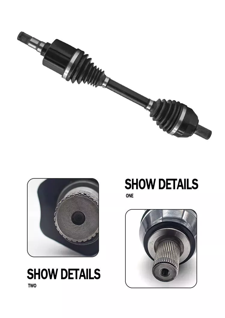
How do manufacturers ensure the compatibility of driveline components with different vehicles?
Manufacturers employ various measures to ensure the compatibility of driveline components with different vehicles. These measures involve careful design, engineering, testing, and standardization processes to meet the specific requirements of each vehicle type. Let’s explore how manufacturers ensure compatibility:
1. Vehicle-Specific Design:
Manufacturers design driveline components with specific vehicle types in mind. Each vehicle type, such as passenger cars, trucks, SUVs, or commercial vehicles, has unique requirements in terms of power output, torque capacity, weight distribution, space constraints, and intended usage. Manufacturers consider these factors during the component design phase to ensure that the driveline components are optimized for compatibility with the intended vehicle type.
2. Engineering and Simulation:
Manufacturers employ advanced engineering techniques and simulation tools to evaluate the performance and compatibility of driveline components. They use computer-aided design (CAD) software and finite element analysis (FEA) simulations to model and analyze the behavior of the components under various operating conditions. This allows them to identify any potential compatibility issues, such as excessive stress, misalignment, or interference, and make necessary design adjustments before moving to the production stage.
3. Prototyping and Testing:
Manufacturers create prototypes of driveline components and subject them to rigorous testing to ensure compatibility. These tests include bench testing, dynamometer testing, and vehicle-level testing. By simulating real-world operating conditions, manufacturers can evaluate the performance, durability, and compatibility of the components. They assess factors such as power transmission efficiency, torque capacity, heat dissipation, noise and vibration levels, and overall drivability to ensure that the components meet the requirements and are compatible with the intended vehicle.
4. Standardization:
Manufacturers adhere to industry standards and specifications to ensure compatibility and interchangeability of driveline components. These standards cover various aspects such as dimensions, material properties, spline profiles, shaft diameters, and mounting interfaces. By following established standards, manufacturers can ensure that their driveline components can be seamlessly integrated into different vehicles from various manufacturers, promoting compatibility and ease of replacement or upgrade.
5. Collaborative Development:
Manufacturers often collaborate closely with vehicle manufacturers during the development process to ensure compatibility. This collaboration involves sharing specifications, design requirements, and performance targets. By working together, driveline manufacturers can align their component designs with the vehicle manufacturer’s specifications, ensuring that the driveline components fit within the vehicle’s space constraints, mating interfaces, and intended usage. This collaborative approach helps optimize compatibility and integration between the driveline components and the vehicle’s overall system.
6. Continuous Improvement:
Manufacturers continuously improve their driveline components based on feedback, field data, and advancements in technology. They gather information from vehicle manufacturers, end-users, and warranty claims to identify any compatibility issues or performance shortcomings. This feedback loop helps drive refinements and enhancements in the design, manufacturing processes, and material selection of the driveline components, ensuring better compatibility and performance in future iterations.
Overall, manufacturers employ a combination of vehicle-specific design, engineering and simulation, prototyping and testing, standardization, collaborative development, and continuous improvement to ensure the compatibility of driveline components with different vehicles. These efforts help optimize power transmission, reliability, and performance, while ensuring a seamless integration of the driveline components into the diverse range of vehicles present in the market.

How do drivelines handle variations in speed and direction during operation?
Drivelines are designed to handle variations in speed and direction during operation, enabling the efficient transfer of power from the engine to the wheels. They employ various components and mechanisms to accommodate these variations and ensure smooth and reliable power transmission. Let’s explore how drivelines handle speed and direction variations:
1. Transmissions:
Transmissions play a crucial role in managing speed variations in drivelines. They allow for the selection of different gear ratios to match the engine’s torque and speed with the desired vehicle speed. By shifting gears, the transmission adjusts the rotational speed and torque delivered to the driveline, enabling the vehicle to operate effectively at various speeds. Transmissions can be manual, automatic, or continuously variable, each with its own mechanism for achieving speed variation control.
2. Clutches:
Clutches are used in drivelines to engage or disengage power transmission between the engine and the driveline components. They allow for smooth engagement during startup and shifting gears, as well as for disconnecting the driveline when the vehicle is stationary or the engine is idling. Clutches facilitate the control of speed variations by providing a means to temporarily interrupt power flow and smoothly transfer torque between rotating components.
3. Differential:
The differential is a key component in drivelines, particularly in vehicles with multiple driven wheels. It allows the wheels to rotate at different speeds while maintaining power transfer. When a vehicle turns, the inside and outside wheels travel different distances and need to rotate at different speeds. The differential allows for this speed variation by distributing torque between the wheels, ensuring smooth operation and preventing tire scrubbing or driveline binding.
4. Universal Joints and CV Joints:
Universal joints and constant velocity (CV) joints are used in drivelines to accommodate variations in direction. Universal joints are typically employed in drivelines with a driveshaft, allowing for the transmission of rotational motion even when there is an angular misalignment between the driving and driven components. CV joints, on the other hand, are used in drivelines that require constant velocity and smooth power transfer at varying angles, such as front-wheel drive vehicles. These joints allow for a consistent transfer of torque while accommodating changes in direction.
5. Transfer Cases:
In drivelines with multiple axles or drivetrains, transfer cases are used to distribute power and torque to different wheels or axles. Transfer cases are commonly found in four-wheel drive or all-wheel drive systems. They allow for variations in speed and direction by proportionally distributing torque between the front and rear wheels, or between different axles, based on the traction requirements of the vehicle.
6. Electronic Control Systems:
Modern drivelines often incorporate electronic control systems to further enhance speed and direction control. These systems utilize sensors, actuators, and computer algorithms to monitor and adjust power distribution, shift points, and torque delivery based on various inputs, such as vehicle speed, throttle position, wheel slip, and road conditions. Electronic control systems enable precise and dynamic management of speed and direction variations, improving traction, fuel efficiency, and overall driveline performance.
By integrating transmissions, clutches, differentials, universal joints, CV joints, transfer cases, and electronic control systems, drivelines effectively handle variations in speed and direction during operation. These components and mechanisms work together to ensure smooth power transmission, optimized performance, and enhanced vehicle control in a wide range of driving conditions and applications.
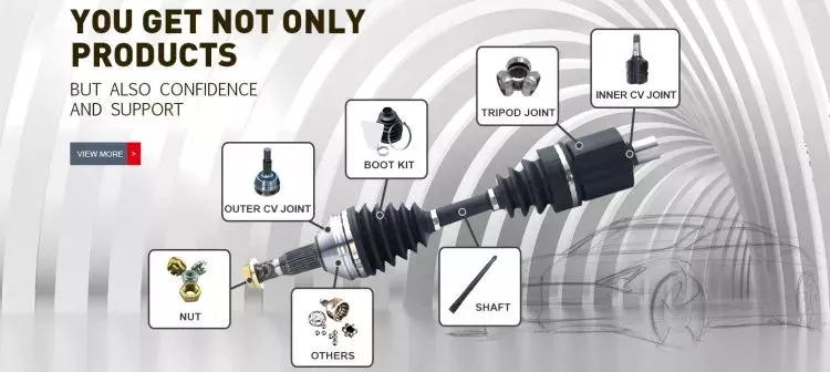
อุตสาหกรรมและยานพาหนะประเภทใดบ้างที่นิยมใช้ระบบส่งกำลัง (drivelines) ในการกระจายพลังงาน?
ระบบส่งกำลัง (Drivelines) ถูกนำมาใช้กันอย่างแพร่หลายในอุตสาหกรรมและยานยนต์ต่างๆ เพื่อการกระจายพลังงาน มีบทบาทสำคัญในการส่งกำลังจากเครื่องยนต์หรือแหล่งพลังงานไปยังชิ้นส่วนที่ต้องการขับเคลื่อน ทำให้เกิดการเคลื่อนที่และการถ่ายทอดแรงบิด ต่อไปนี้เป็นคำอธิบายโดยละเอียดเกี่ยวกับอุตสาหกรรมและยานยนต์ที่มักใช้ระบบส่งกำลังเพื่อการกระจายพลังงาน:
1. อุตสาหกรรมยานยนต์: อุตสาหกรรมยานยนต์ใช้ระบบส่งกำลังอย่างแพร่หลายในรถยนต์นั่งส่วนบุคคล รถยนต์เพื่อการพาณิชย์ และรถยนต์ออฟโรด ระบบส่งกำลังเป็นส่วนประกอบพื้นฐานของยานยนต์ ทำหน้าที่ส่งกำลังจากเครื่องยนต์ไปยังล้อ พบได้ในยานยนต์หลายประเภท เช่น รถเก๋ง รถ SUV รถกระบะ รถตู้ รถบัส และรถบรรทุกขนาดใหญ่ ระบบส่งกำลังในอุตสาหกรรมยานยนต์ได้รับการออกแบบมาเพื่อให้การกระจายกำลังมีประสิทธิภาพ เพิ่มประสิทธิภาพของยานยนต์ และรับประกันการเร่งความเร็วและการควบคุมที่ราบรื่น
2. อุตสาหกรรมเกษตร: ระบบส่งกำลังมีความสำคัญอย่างยิ่งในอุตสาหกรรมการเกษตร สำหรับเครื่องจักรและอุปกรณ์ทางการเกษตรต่างๆ รถแทรกเตอร์ รถเกี่ยวข้าว เครื่องเก็บเกี่ยว และเครื่องจักรทางการเกษตรอื่นๆ อาศัยระบบส่งกำลังในการถ่ายทอดกำลังจากเครื่องยนต์ไปยังล้อหรือตีนตะขาบ ระบบส่งกำลังในเครื่องจักรทางการเกษตรมักประกอบด้วยชุดส่งกำลังแบบ PTO (Power Take-Off) ซึ่งช่วยให้สามารถเชื่อมต่ออุปกรณ์เสริมต่างๆ เช่น ไถ เครื่องหว่านเมล็ด และเครื่องอัดฟางได้ ระบบส่งกำลังเหล่านี้ได้รับการออกแบบมาเพื่อรองรับแรงบิดสูง ให้แรงฉุดในสภาพพื้นที่ที่ยากลำบาก และช่วยให้การทำฟาร์มมีประสิทธิภาพ
3. อุตสาหกรรมการก่อสร้างและเหมืองแร่: ระบบส่งกำลังถูกนำมาใช้กันอย่างแพร่หลายในอุปกรณ์ก่อสร้างและเหมืองแร่ โดยทำหน้าที่กระจายกำลังและเพิ่มความคล่องตัวให้กับเครื่องจักรขนาดใหญ่ รถขุด รถดันดิน รถตักล้อ รถบรรทุกดัมพ์ และยานพาหนะก่อสร้างและเหมืองแร่อื่นๆ ต่างพึ่งพาระบบส่งกำลังในการถ่ายทอดกำลังจากเครื่องยนต์ไปยังล้อหรือตีนตะขาบ ระบบส่งกำลังในอุตสาหกรรมเหล่านี้ได้รับการออกแบบมาให้ทนทานต่อสภาวะการใช้งานที่รุนแรง ส่งแรงบิดและแรงฉุดสูง และให้กำลังที่จำเป็นสำหรับการขุด การขนส่ง และการขนถ่ายวัสดุ
4. อุปกรณ์อุตสาหกรรม: อุปกรณ์และเครื่องจักรอุตสาหกรรมต่างๆ ใช้ระบบส่งกำลังเพื่อกระจายพลังงาน ซึ่งรวมถึงอุปกรณ์ขนถ่ายวัสดุ เช่น รถยกและเครน รถบรรทุกอุตสาหกรรม ระบบลำเลียง และยานพาหนะอุตสาหกรรมที่ใช้ในคลังสินค้า โรงงาน และศูนย์กระจายสินค้า ระบบส่งกำลังในอุปกรณ์อุตสาหกรรมได้รับการออกแบบมาเพื่อให้การส่งกำลังมีประสิทธิภาพ การควบคุมที่แม่นยำ และความคล่องตัวในพื้นที่จำกัด ทำให้การทำงานราบรื่นและเชื่อถือได้ในสภาพแวดล้อมทางอุตสาหกรรม
5. ยานพาหนะออฟโรดและยานพาหนะเพื่อการพักผ่อนหย่อนใจ: ระบบส่งกำลัง (Drive-by-Side) เป็นอุปกรณ์ที่ใช้กันทั่วไปในยานพาหนะออฟโรดและยานพาหนะเพื่อการพักผ่อนหย่อนใจ รวมถึงรถเอทีวี (ATV), รถยูที (UTV), รถจักรยานยนต์วิบาก, รถสโนว์โมบิล และเรือเพื่อการพักผ่อนหย่อนใจ ยานพาหนะเหล่านี้ต้องการระบบส่งกำลังเพื่อถ่ายทอดกำลังจากเครื่องยนต์ไปยังล้อ ตีนตะขาบ หรือใบพัด ทำให้สามารถขับขี่บนทางวิบาก มีแรงฉุด และขับเคลื่อนในน้ำได้ ระบบส่งกำลังในยานพาหนะออฟโรดและยานพาหนะเพื่อการพักผ่อนหย่อนใจได้รับการออกแบบมาเพื่อความทนทาน ประสิทธิภาพ และการควบคุมที่ดียิ่งขึ้นในภูมิประเทศที่ท้าทายและสภาพแวดล้อมเพื่อการพักผ่อนหย่อนใจ
6. อุตสาหกรรมรถไฟ: ระบบส่งกำลังถูกนำมาใช้ในหัวรถจักรและขบวนรถไฟเพื่อกระจายกำลังและขับเคลื่อน มีหน้าที่ส่งกำลังจากเครื่องยนต์ของหัวรถจักรไปยังล้อหรือระบบขับเคลื่อน ทำให้รถไฟสามารถเคลื่อนที่บนรางได้ ระบบส่งกำลังในอุตสาหกรรมรถไฟได้รับการออกแบบมาเพื่อรองรับแรงบิดสูง เพื่อให้การส่งกำลังมีประสิทธิภาพ และอำนวยความสะดวกในการเดินรถไฟที่ปลอดภัยและเชื่อถือได้
7. อุตสาหกรรมทางทะเล: ระบบส่งกำลังเป็นส่วนประกอบสำคัญในเรือเดินทะเล รวมถึงเรือเล็ก เรือยอชต์ เรือเดินสมุทร และยานพาหนะทางน้ำอื่นๆ ระบบส่งกำลังของเรือใช้สำหรับส่งกำลังจากเครื่องยนต์ไปยังใบพัดหรือเจ็ทน้ำ เพื่อสร้างแรงขับและแรงขับเคลื่อน ระบบส่งกำลังได้รับการออกแบบให้ทนทานต่อสภาพแวดล้อมทางทะเลที่มีฤทธิ์กัดกร่อน รับแรงบิดสูง และรับประกันการส่งกำลังที่มีประสิทธิภาพสำหรับการขับเคลื่อนทางทะเล
นี่คือตัวอย่างอุตสาหกรรมและยานพาหนะบางส่วนที่มักใช้ระบบส่งกำลังในการส่งถ่ายพลังงาน ระบบส่งกำลังเป็นชิ้นส่วนอเนกประสงค์ที่ช่วยให้การส่งกำลัง การเคลื่อนที่ และประสิทธิภาพการทำงานมีประสิทธิภาพในหลากหลายการใช้งาน ซึ่งมีส่วนช่วยในการทำงานและผลิตภาพของอุตสาหกรรมและยานพาหนะต่างๆ


editor by CX 2023-12-19